Superconductive coil assembly having improved cooling efficiency

a superconductive coil and cooling efficiency technology, applied in the direction of superconducting magnets/coils, transformers/inductance details, magnetic bodies, etc., can solve the problems of many time to cool, and many time to cool the coil, so as to achieve a stable and continuous cryogenic state and improve the structure

Inactive Publication Date: 2007-08-16
DOOSAN HEAVY IND & CONSTR CO LTD
View PDF4 Cites 15 Cited by
  • Summary
  • Abstract
  • Description
  • Claims
  • Application Information

AI Technical Summary

Benefits of technology

[0011] Accordingly, the present invention has been made to solve the above-mentioned problems occurring in the prior art, and an object of the present invention is to provide a superconductive coil assembly having an improved structure capable of stably and continuously maintaining a cryogenic state by forming an optimized heat transfer path along the coil in conduction cooling through the provision of an electrically insulated heat transfer plate to the opposite sides of the coil.

Problems solved by technology

Because the direct cooling method may cause corrosion to the coil by the direct contact of the coil with the coolants, the conduction cooling method is generally used.
Such conventional coil assembly has advantage in structural reinforcement, but also has a problem in that because of low heat conductivity in character of GFRP sheet, if several coil assemblies are used while being overlapped to each other, the heat transfer between coils is not smoothly implemented so it takes so many time to cool them.
Further, if a single coil assembly unit is used, upon conduction cooling, the heat transfer path between the cooling source and the coil horizontally extends at full length from the bobbin to the outside of the coil through the inside of the coil, so that it causes a problem in that it takes so many time to cool the coil as well as there is generated a temperature gradient between the inside and outside of the coil.
If the temperature gradient there between is large, the coil may be quenched at its outside, being damaged.

Method used


Image

  • Superconductive coil assembly having improved cooling efficiency
  • Superconductive coil assembly having improved cooling efficiency
  • Superconductive coil assembly having improved cooling efficiency

Examples


Embodiment Construction

[0024] Hereinafter, preferred embodiments of the present invention will be described with reference to the accompanying drawings.

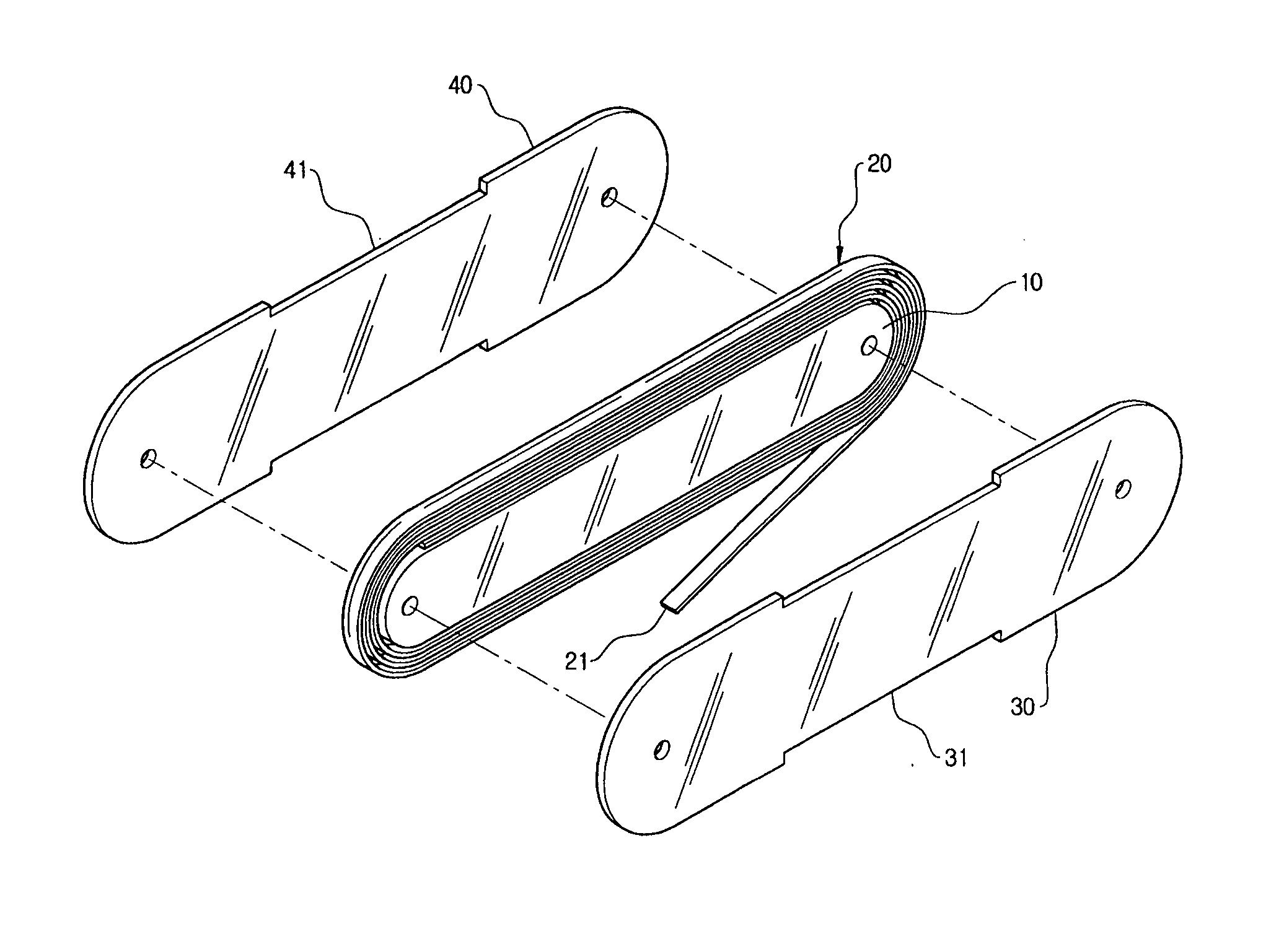
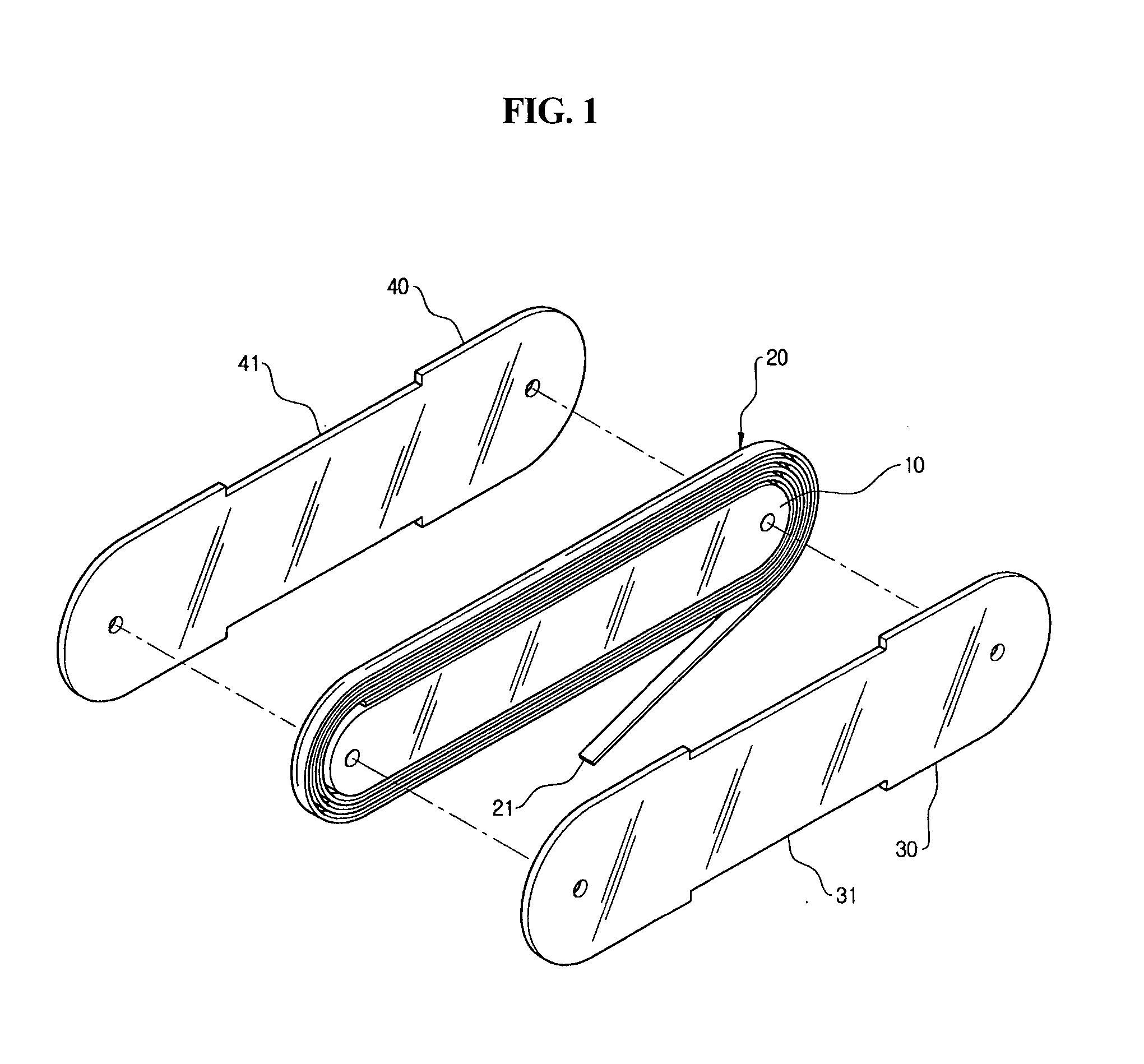
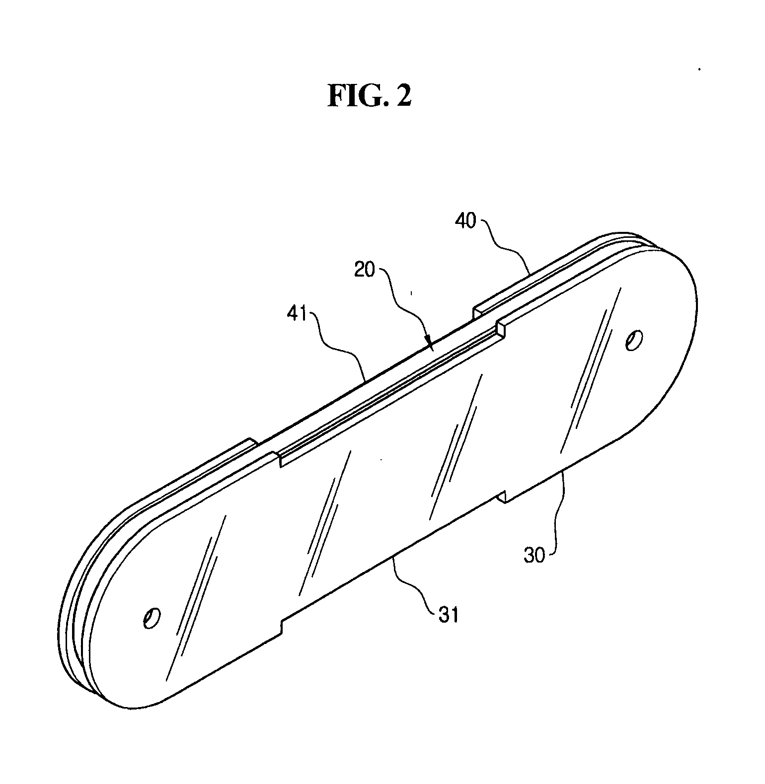
[0025]FIG. 1 is an exploded perspective view of a superconductive coil assembly according to an embodiment of the present invention, and FIG. 2 is a perspective view of the superconductive coil assembly of FIG. 1 in assembled state.

[0026] The superconductive coil assembly of the present embodiment is so-called “single pan cake” type coil assembly. As shown in FIG. 1, the superconductive coil assembly includes a bobbin 10, a coil 20 formed by winding a superconductive wire 21 several times around the bobbin 10, and a pair of heat transfer plates 30 and 40 installed to cover both the sides of the bobbin 10 and the coil 20.

[0027] The superconductive wire 21 is rectangular in cross section unlike a normal conductor so as to prevent the degradation in superconducting performance even upon application of an external shock or an excessive physical force, becau...


PUM

PropertyMeasurementUnit
temperatureaaaaaaaaaa
superconductiveaaaaaaaaaa
thermal conductivityaaaaaaaaaa

Abstract

A superconductive coil assembly has a bobbin, a coil provided such that a superconductive wire is wound several times around the bobbin, and a pair of heat transfer plates installed to cover the opposite sides of the bobbin and the coil. The heat transfer plate is made of metal material with high thermal conductivity, such as copper or aluminum, and a portion thereof abutted upon the side of the coil is coated with electric insulating material. If adapted to a generator, an electric motor, and so on, the plurality of superconductive coil assemblies is used while being overlapped. In this case, a connection recess is provided to at least one heat transfer plate to enable a portion of the side of the coil to be exposed outside, in order for electrical connection with another superconductive coil assembly. By the construction of the superconductive coil assembly, a heat transfer path between the cooling source and the superconductive coil is diversified by the heat transfer plate, thereby shortening a cooling time of the superconductive coil as well as improving cryogenic operation stability. Further, the heat transfer plate protects the side of the superconductive coil so that even when the superconductive coil is applied to the inside of the rotor of a generator or an electric motor, and operates under the centrifugal force, it can operate stably and continuously.

Description

CROSS-REFERENCE TO RELATED APPLICATION [0001] This application claims all benefits of Korean Patent Application No. 10-2006-13529, filed on Feb. 13, 2006 in the Korean Intellectual Property Office, the disclosures of which is incorporated herein by reference.BACKGROUND OF THE INVENTION [0002] 1. Field of the Invention [0003] The present invention relates to a superconductive coil assembly used in a superconducting generator or electric motor, and more particularly to a superconductive coil assembly having improved cooling efficiency through the modification of a heat transfer path between a coil and a cooling source. [0004] 2. Description of the Prior Art [0005] Generally, superconductive coils are the coils which have superconductivity at very low temperature below approximately −196° C., and are mainly used in high current flow and magnetic field appliances using a superconducting characteristic in the cryogenic environment. [0006] Such superconductive coil requires that the cryog...

Claims


Application Information

Patent Timeline
Patent Type & Authority Applications(United States)
IPC IPC(8): H01F6/00
CPCH01F6/04H01F6/06H01F41/0687H01F27/2847H01F27/2876H01F27/22H01F41/098H02K55/04
Inventor PARK, HEUI-JOOKIM, YEONG-CHUNMOON, TAE-SUNKWON, WOON-SIK
Owner DOOSAN HEAVY IND & CONSTR CO LTD
Why Eureka
Try Eureka