Printing device

a printing device and printing plate technology, applied in printing, other printing apparatus, etc., can solve the problems of recording paper, recording paper, and the angle at which the recording paper contacts the platen roller to change, so as to suppress the variation in the conveyance force to due to the change in the contact angle, convey stably, and the recording paper cannot go slack or deform.

Active Publication Date: 2016-10-18
SEIKO EPSON CORP
View PDF10 Cites 0 Cited by
  • Summary
  • Abstract
  • Description
  • Claims
  • Application Information

AI Technical Summary

Benefits of technology

[0010]Therefore the conveyance path between the conveyance roller and the driven roller is not affected by a change in the diameter of the paper roll, and the paper roll is held in the same path even if it rolls inside the roll paper holder. The orientation of the recording paper supplied to the conveyance roller can therefore be kept constant. Furthermore, because the recording paper in contact with the driven roller curves, the orientation of the recording paper is stabilized by the stiffness of the recording paper, and there is little chance of the recording paper going slack or deforming. Furthermore, because the angle of rotation through which the recording paper contacts the conveyance roller can be kept constant, variation in the conveyance force to due change in the contact angle can be suppressed. The recording paper can therefore be conveyed stably, and a drop in the conveyance precision can be suppressed. The conveyance load can also be reduced because the driven roller is a rotating body.
[0011]Furthermore, the path of the recording paper in contact with the driven roller curves, and a paper detection member for detecting the recording paper contacts the recording paper from the inside circumference side of this part (first curved path). With this direction of contact, there is little chance of the paper detection member changing the shape of the recording paper or creating detection marks or wrinkles. The recording paper can therefore be conveyed stably. In addition, because the recording paper reliably passes through a curved path defined by the driven roller, the recording paper can be reliably detected. The printer can also be built compactly by detecting the paper at a part where the paper path curves.

Problems solved by technology

When slack develops in the recording paper on the path in the roll paper printer from inside the roll paper holder to the platen roller, the recording paper cannot be conveyed stably and conveyance precision may drop.
The path of the recording paper may also change when the diameter of the paper roll changes or the position in which the roll paper printer is used changes, and this may cause the angle at which the recording paper contacts the platen roller to change.
When this happens, the paper feed force is not stable and conveyance precision may drop.
However, the recording paper may be deformed by contact with the paper detection lever in this type of paper detection unit, potentially leaving detection marks on the paper or causing wrinkles.
Such deformation of the recording paper can be prevented by defining the paper path with guide panels, for example, but disposing the guide panels so they do not interfere with the paper detection lever is difficult and incompatible with reducing printer size.
If the paper path from the roll paper holder to the platen roller changes according to the diameter of the paper roll or the position in which the printer is installed for use, simply detecting the paper with a paper detection lever becomes difficult.

Method used


Image

  • Printing device
  • Printing device
  • Printing device

Examples


Embodiment Construction

[0021]Exemplary embodiments of the present disclosure are described below with reference to the accompanying drawings.

General Configuration

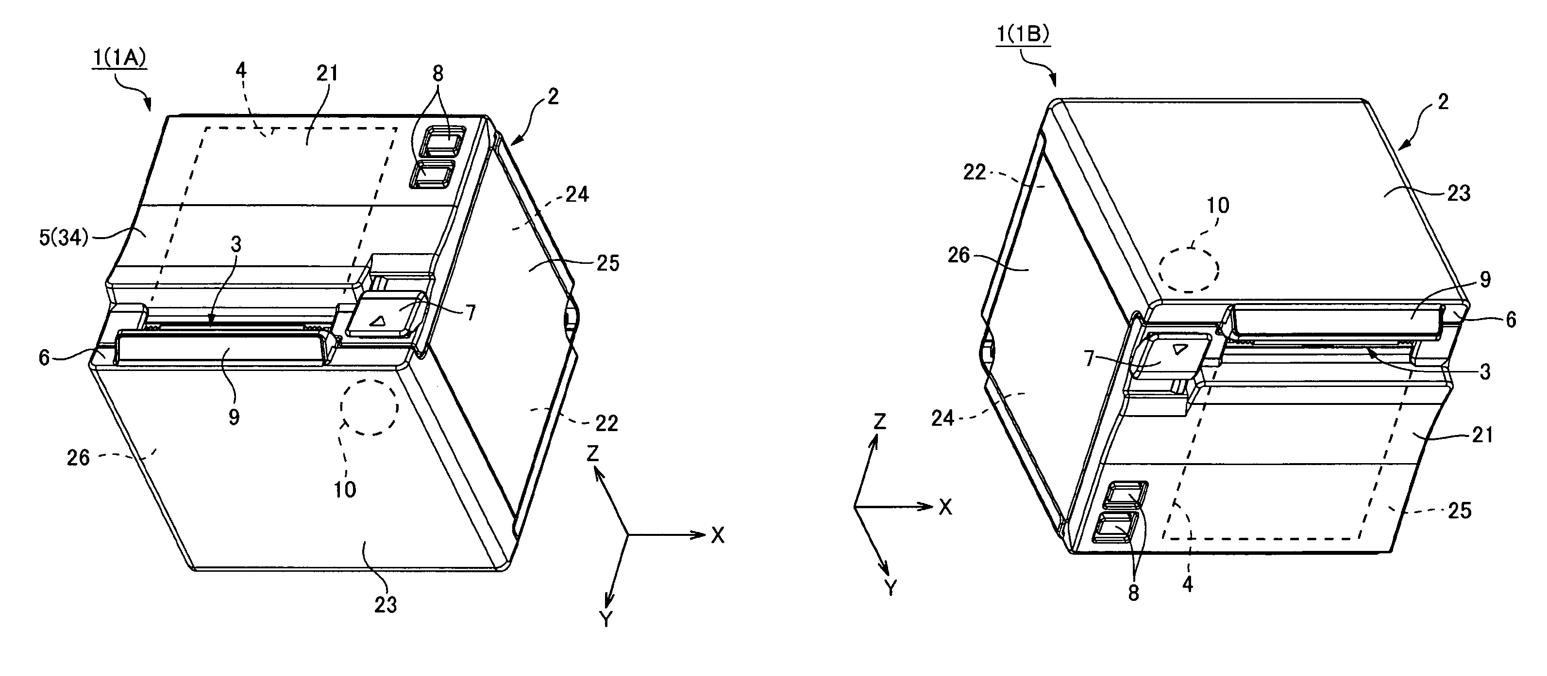
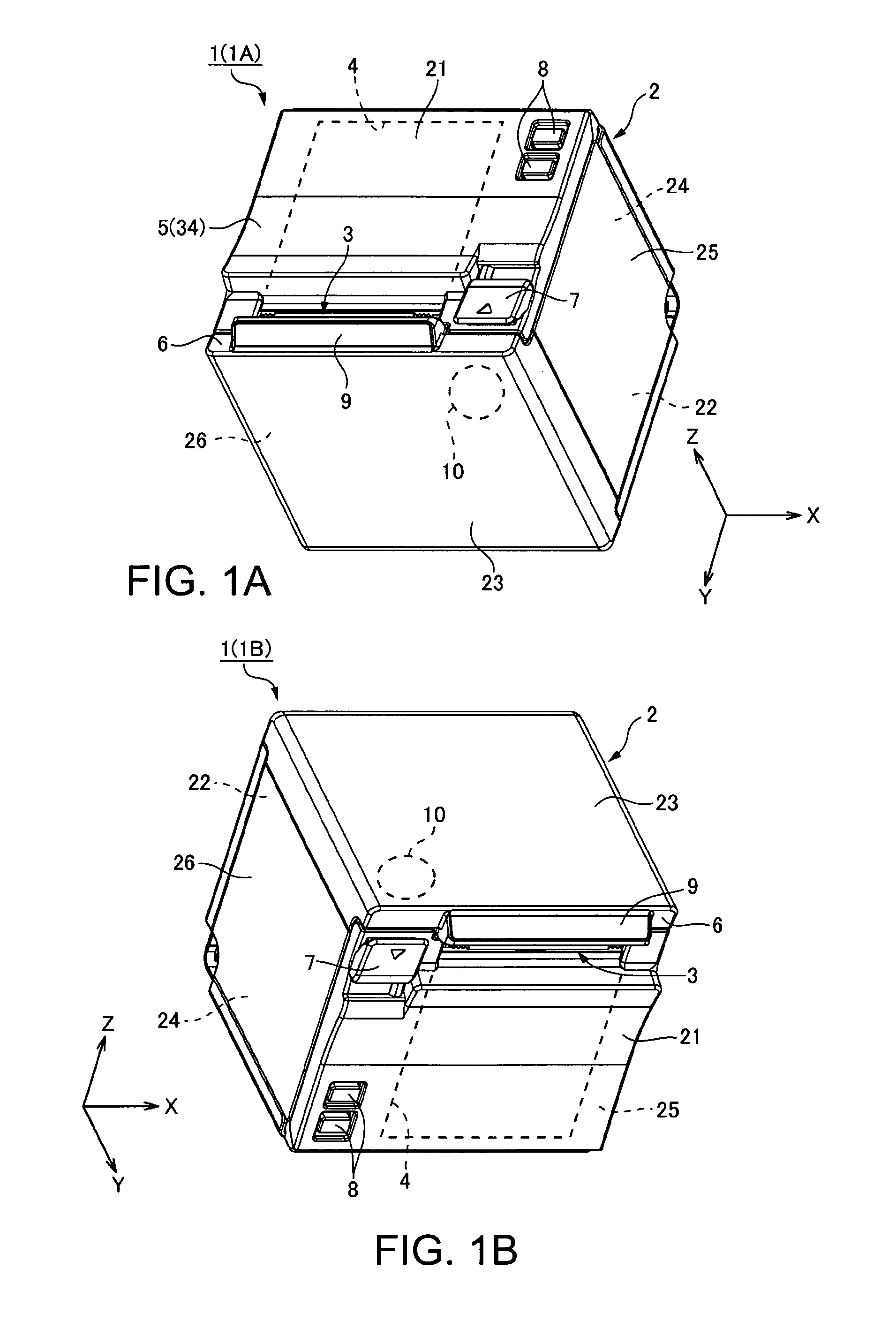
[0022]FIGS. 1A and 1B are external oblique views of a roll paper printer according to this embodiment of the disclosure. This embodiment of the disclosure is described with reference to three mutually perpendicular axes, the transverse axis X, longitudinal axis Y, and vertical axis Z. In the three directions XYZ shown in FIGS. 1A and 1B, the direction of the arrow denotes the positive (+, forward) direction, and the direction opposite the arrow is the negative (−, reverse) direction.

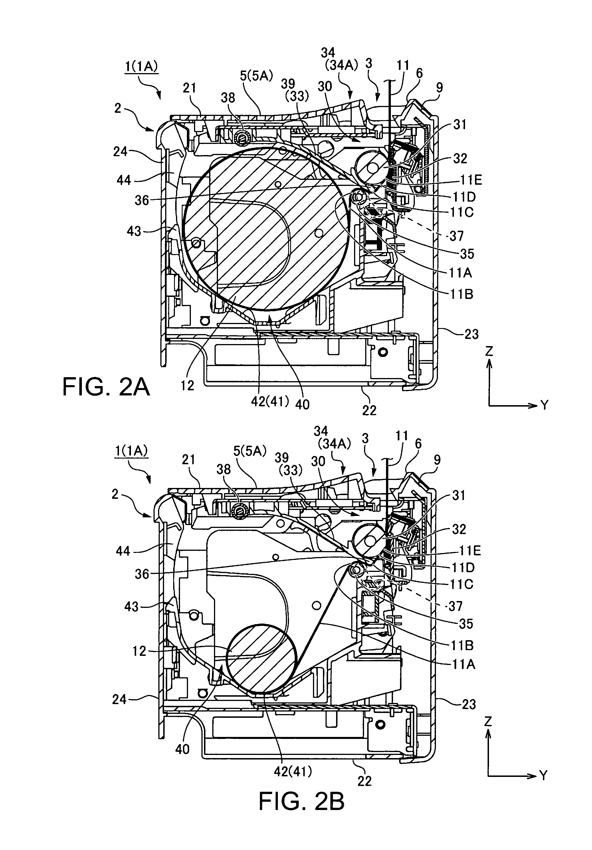
[0023]The roll paper printer 1 (printing device) is placed on its XY surface, which is a flat surface, for use. The roll paper printer 1 stores a paper roll 12 (see FIGS. 2A, 2B, 3A and 3B) of continuous recording paper 11 wound into a roll, and prints on the recording paper 11 delivered from the paper roll 12.

[0024]The roll paper printer 1 has a basically rectangular...


PUM


Abstract

A roll paper printer has a roll paper holder that holds a paper roll of recording paper wound into a roll; a platen roller that conveys recording paper delivered from the paper roll; a printhead that prints on the recording paper conveyed by the platen roller; a delivery roller around which the recording paper travels between the paper roll and platen roller; and a paper detection lever that detects the recording paper; the paper detection lever being disposed on the inside circumference side of a first curved path through which the recording paper is conveyed in contact with the delivery roller.

Description

[0001]Priority is claimed under 35 U.S.C. §119 to Japanese Application No. 2014-261886 filed Dec. 25, 2014.BACKGROUND[0002]1. Technical Field[0003]The present disclosure relates to a printing device that delivers recording paper from a paper roll held in a roll paper holder and prints with a printhead.[0004]2. Related Art[0005]Roll paper printers (printing devices) that hold a roll of continuous recording paper wound into a roll, and deliver the paper from the paper roll for printing, are common. In the roll paper printer described in JP-A-H4-308776, for example, the recording paper delivered from a paper roll inside a roll paper holder passes between a platen roller and printhead, and is conveyed by rotation of the platen roller (conveyance roller). The roll paper printer disclosed in JP-A-H4-308776 can be used in two positions, with the back side down, or with the bottom down. The printer in JP-A-H4-308776 has a shape that can hold the paper roll stable when the roll diameter beco...

Claims


Application Information

Patent Timeline
Patent Type & Authority Patents(United States)
IPC IPC(8): B41J11/04B41J11/00B41J15/00
CPCB41J11/04B41J11/0095B41J11/009B41J15/00B41J15/04B41J15/042
Inventor ISHIMORI, HIROYUKI
Owner SEIKO EPSON CORP
Why Eureka
Try Eureka