Reducer and electric power steering apparatus having the same

a technology of electric power steering and reducing device, which is applied in the direction of gearing details, gearing, transportation and packaging, etc., can solve the problems of disadvantageous layout and inevitable protruding motor, and achieve the effect of convenient adjustment and compact form

Active Publication Date: 2016-10-18
HL MANDO CORP
View PDF8 Cites 3 Cited by
  • Summary
  • Abstract
  • Description
  • Claims
  • Application Information

AI Technical Summary

Benefits of technology

[0012]Accordingly, the present invention has been made to solve the above-mentioned problems occurring in the prior art, and an object of the present invention is to provide a reducer which improves a conventional configuration, in which a motor inevitably protrudes since a motor shaft, an input shaft, a driving shaft, a pinion shaft, etc. are coaxially arranged, to be capable of preventing the motor from interfering with other structures such that the layout configuration in an apparatus can be compactly formed, and an electric power steering apparatus having the reducer.
[0013]In addition, another object of the present invention is to provide a reducer in which the number of teeth of a step gear, a fixed ring gear, a movable ring gear or the like can be adjusted such that a rotational force generated by a motor and transmitted to a pinion shaft can be easily adjusted, and an electric power steering apparatus having the reducer.
[0017]According to the present invention, since the motor shaft, the input shaft, the driving shaft, and the pinion shaft are coaxially arranged, a conventional configuration, in which a motor inevitably protrudes, can be improved to prevent the motor from interfering with the other structures. Therefore, a layout configuration in an apparatus can be compactly formed.
[0018]In addition, according to the present invention, the number of teeth of each of the step gear, the fixed ring gear, and the movable ring gear can be adjusted such that the rotational force generated by the motor and transferred to the pinion shaft can be easily adjusted.

Problems solved by technology

Thus, when the components are equipped in a vehicle, the motor inevitably protrudes to interfere with other structures, which is disadvantageous in terms of the layout.

Method used


Image

  • Reducer and electric power steering apparatus having the same
  • Reducer and electric power steering apparatus having the same
  • Reducer and electric power steering apparatus having the same

Examples


Embodiment Construction

[0026]Hereinafter, exemplary embodiments of the present invention will be described with reference to the accompanying drawings.

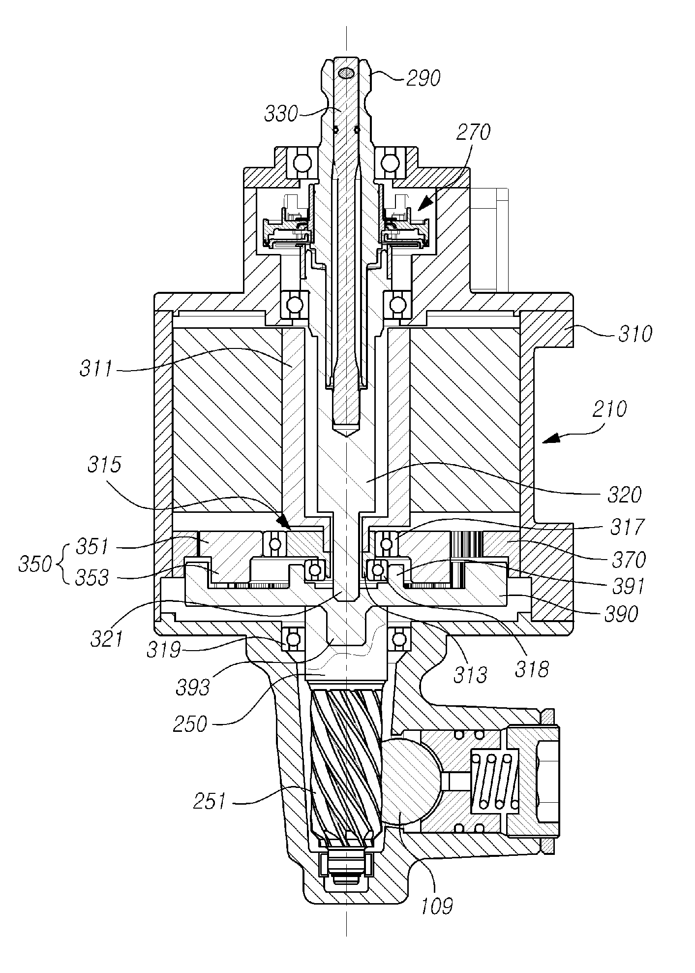
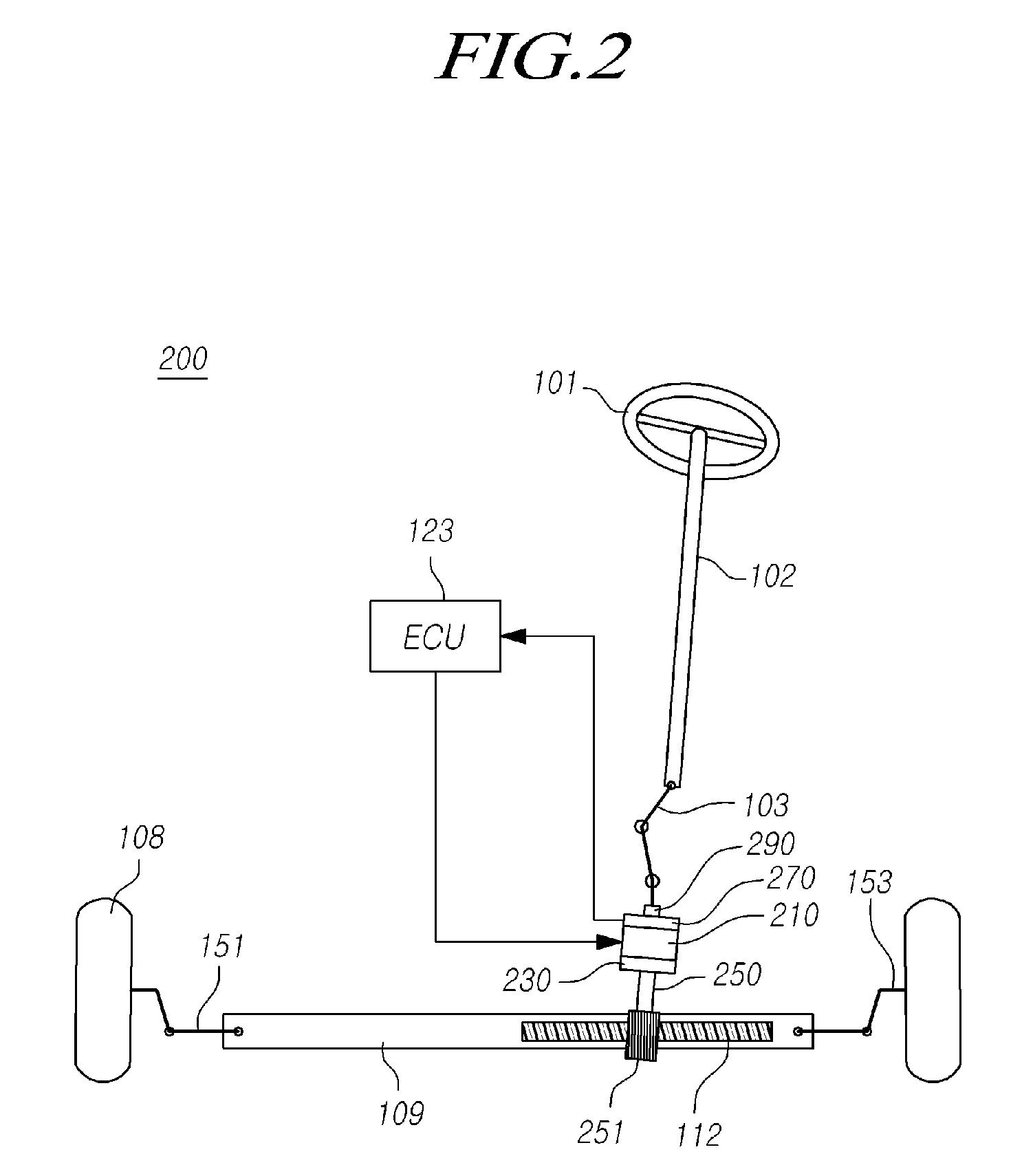
[0027]FIG. 2 is a view illustrating a configuration of an electric power steering apparatus provided with a reducer according to an exemplary embodiment of the present invention. FIG. 3 is a cross-sectional view for a part of FIG. 2. FIG. 4 is a perspective view of an example of a reducer which may be employed in the configuration illustrated in FIG. 2. FIG. 5 is a perspective view illustrating another example of a reducer of FIG. 2 which may be employed in the configuration illustrated in FIG. 2. FIGS. 6 and 7 are exploded perspective views of the reducer of FIG. 5.

[0028]As illustrated in the drawings, a reducer 230 according to an exemplary embodiment of the present invention includes: an eccentric cam 315 formed with a coupling hole 613 in which one end of a hollow motor shaft 311 of a motor 210 is fitted; a step gear 350 including a large-diameter porti...


PUM


Abstract

Disclosed are a reducer and an electric power steering apparatus having the same. According to the present invention, an input shaft, a driving shaft, and a pinion shaft are coaxially arranged. Thus, a conventional configuration, in which a motor inevitably protrudes, can be improved to prevent the motor from interfering with the other structures. Therefore, a layout configuration in an apparatus can be compactly formed.

Description

CROSS-REFERENCE TO RELATED APPLICATION[0001]This application claims priority from and the benefit under 35 U.S.C. §119(a) of Korean Patent Application No. 10-2013-0040763, filed on Apr. 15, 2013, which is hereby incorporated by reference for all purposes as if fully set forth herein.BACKGROUND OF THE INVENTION[0002]1. Field of the Invention[0003]The present invention relates to a reducer and an electric power steering apparatus having the same, and more particularly to a reducer which improves a conventional configuration, in which a motor inevitably protrudes since a motor shaft, an input shaft, a driving shaft, a pinion shaft, etc. are coaxially arranged, to be capable of preventing the motor from interfering with other structures such that a layout configuration in an apparatus can be compactly formed, and an electric power steering apparatus having the reducer.[0004]2. Description of the Prior Art[0005]FIG. 1 is a view illustrating a configuration of a conventional electric powe...

Claims


Application Information

Patent Timeline
Patent Type & Authority Patents(United States)
IPC IPC(8): B62D5/04F16H1/32
CPCB62D5/0403B62D5/0415F16H1/32F16H1/321F16H2001/324B62D5/04F16H37/12F16H57/023B62D3/12F16H1/28
Inventor KO, KYUNG MINPARK, JUNG SIKCHOI, SEONG HO
Owner HL MANDO CORP
Why Eureka
Try Eureka