Pushcart

a pushcart and push-cart technology, applied in the field of push-carts, can solve problems such as unintended movement of the walking fram

Active Publication Date: 2016-10-25
MURATA MFG CO LTD
View PDF7 Cites 6 Cited by
  • Summary
  • Abstract
  • Description
  • Claims
  • Application Information

AI Technical Summary

Benefits of technology

[0007]Accordingly, the present disclosure provides a pushcart that prevents unintended movement thereof in the case where a user attempts to raise a front wheel thereof from a ground surface.
[0010]In this configuration, a user holds the holding portion or places the forearms or the like on the holding portion, and moves the pushcart in a forward / backward direction on a ground surface. The pushcart performs inverted pendulum control in the first control mode to assist the user in walking.
[0016]Therefore, according to the above pushcart, the pushcart can be prevented from unintended movement when the user attempts to raise the second wheel from the ground surface.
[0021]A blocking unit can be included for preventing the supporter from rotating with an angle which is no less than a predetermined angle in the pitch direction with respect to the main body or the rotational shaft of the first wheel.
[0022]In this configuration, after the second wheel has reached the upper side of the step, the supporter is rotated until the blocking unit prevents the rotation thereof while the second wheel supported by the supporter serving as a fulcrum, whereby the user can lift the first wheel onto the upper side of the step.
[0027]According to the present disclosure, in the case where a user attempts to raise the second wheel of the pushcart from a ground surface, unintended movement of the pushcart can be prevented.

Problems solved by technology

As such, in the case where the user attempts to raise only the auxiliary wheel (front wheel) of the walking frame from the ground surface, there is a possibility that the pair of wheels (rear wheels) rotates and brings about unintended movement of the walking frame.

Method used


Image

  • Pushcart
  • Pushcart
  • Pushcart

Examples


first embodiment

[0043]Hereinafter, a pushcart 100 according to the present disclosure will be described.

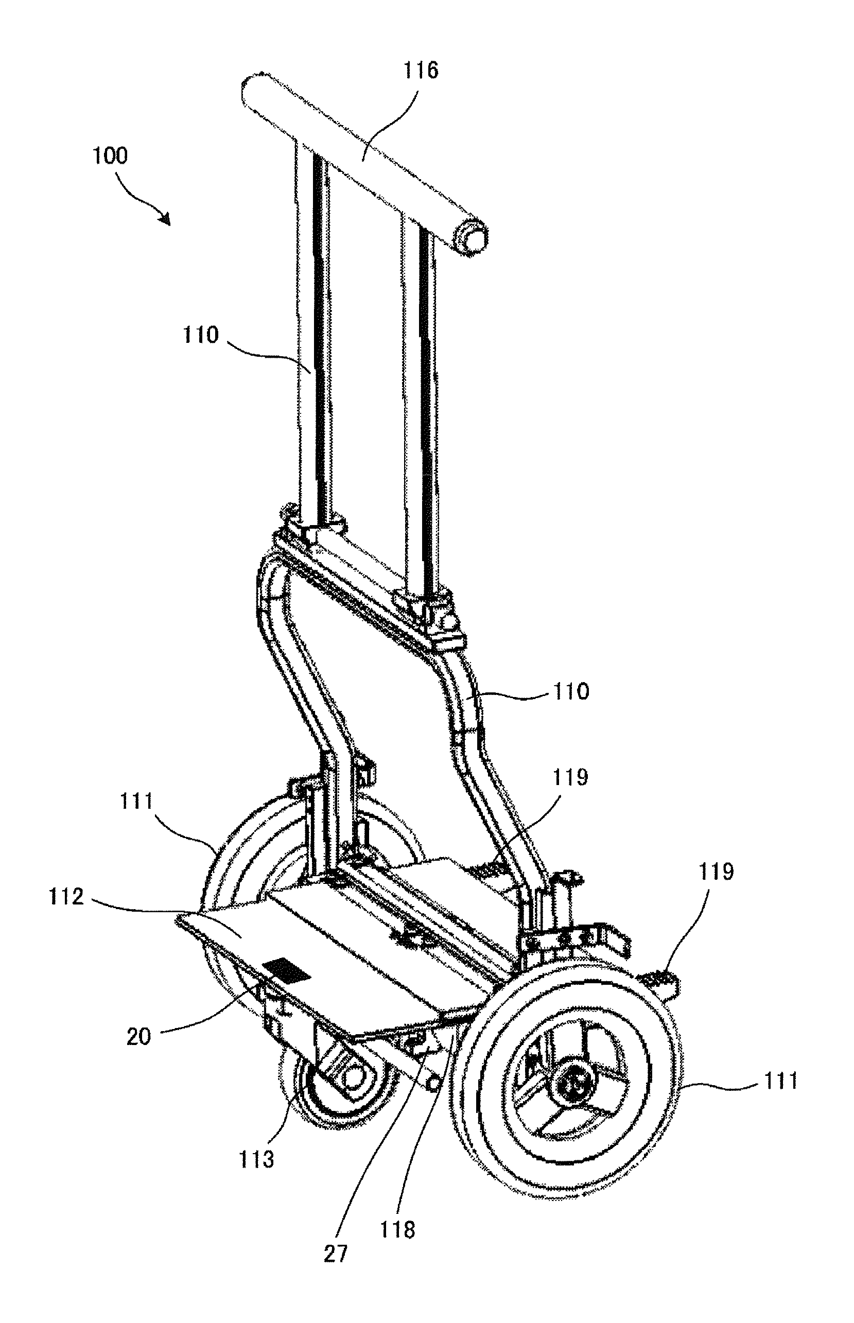
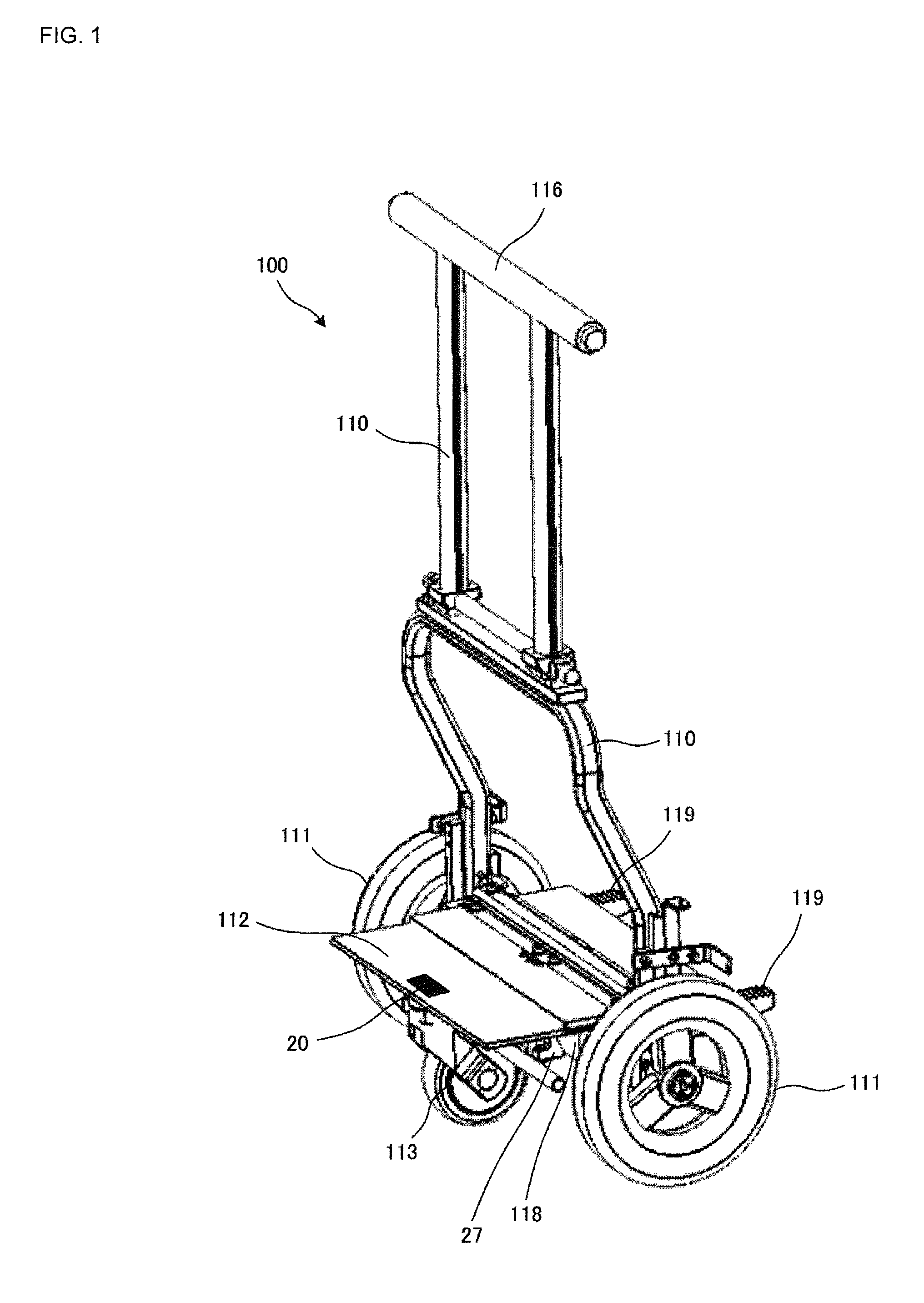
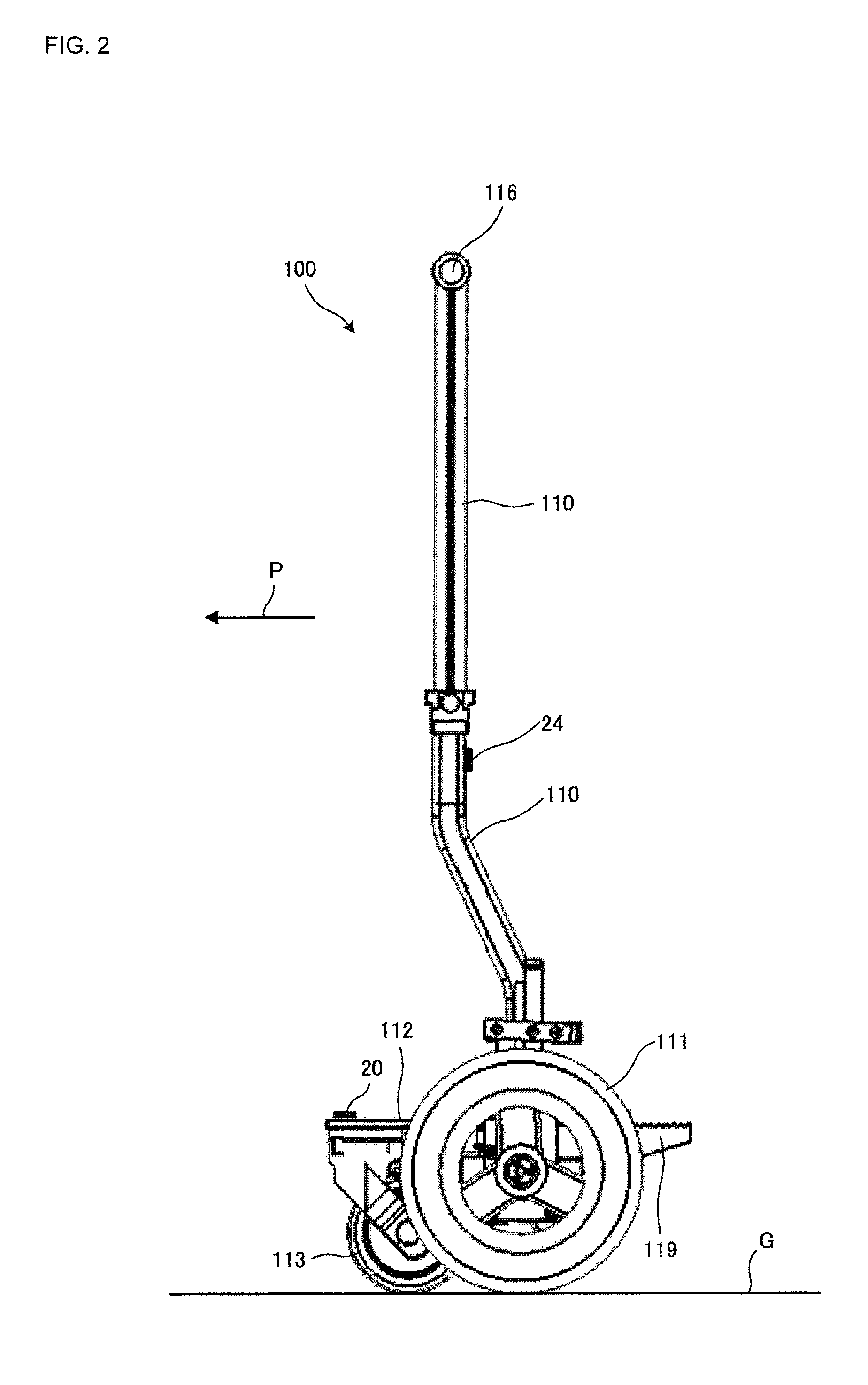
[0044]FIG. 1 is an external appearance perspective view of a pushcart 100 according to a first embodiment of the present disclosure. FIG. 2 is a side view of the pushcart 100 shown in FIG. 1. FIG. 3 is a front view of the pushcart 100 shown in FIG. 1. FIG. 4 is a schematic side view of the pushcart 100 shown in FIG. 1.

[0045]The pushcart 100 includes a main body 110, a pair of main wheels 111, a supporter 112, an auxiliary wheel 113, a blocking unit 118, a switching lever 119, a slope angle sensor 20, a gyrosensor 24, a driver unit 25, and a supporter rotary encoder 27.

[0046]In this embodiment, the pushcart 100 is a walking frame for assisting a user such as an aged person, a disabled person, or the like in walking. In addition, the pushcart 100 is used, for example, as a pushchair, a shopping cart, or the like.

[0047]Here, the main wheels 111 correspond to “first wheel” of the present disclosure. ...

second embodiment

[0099]Hereinafter, a pushcart 200 according to the present disclosure will be described.

[0100]FIG. 12 is a schematic side view of the pushcart 200 according to the second embodiment of the present disclosure.

[0101]The pushcart 200 according to the second embodiment differs from the pushcart 100 according to the first embodiment in a point that a switching wire 219 is provided in place of the switching lever 119. One end of the switching wire 219 is connected to the holding portion 116 while the other end of the switching wire 219 is connected to the other end portion of the supporter 112 on the side where the supporter 112 is not supported by the main wheels 111. Since other constituent elements are the same as those of the pushcart 100, descriptions thereof are omitted herein.

[0102]In the present disclosure, in the case where the user U attempts to raise only the auxiliary wheel 113 of the pushcart 200 from the ground surface G so as to negotiate the step S, the user U pulls the sw...

third embodiment

[0104]Hereinafter, a pushcart 300 according to the present disclosure will be described.

[0105]FIG. 13 is a schematic side view of the pushcart 300 according to the third embodiment of the present disclosure.

[0106]The pushcart 300 according to the third embodiment differs from the pushcart 100 according to the first embodiment in a point that a driver unit 319 and a mode-exchange switch are provided in place of the switching lever 119. The driver unit 319 corresponds to “second driver unit” of the present disclosure and the mode-exchange switch corresponds to “switching unit” of the present disclosure. Since other constituent elements are the same as those of the pushcart 100, descriptions thereof are omitted herein.

[0107]To be more specific, the driver unit 319 for actively rotating the supporter 112 in the pitch direction is provided in the supporter 112.

[0108]The mode-exchange switch to carry out switching between the first control mode and the second control mode is provided in t...


PUM


Abstract

A pushcart includes a main body, a pair of main wheels, a supporter, an auxiliary wheel, a blocking unit, a switching lever, a slope angle sensor, a gyrosensor, a driver unit, and a supporter rotary encoder. The supporter rotary encoder detects an intersecting angle which is an angle formed by the main body and the supporter, and outputs the detected result to a controller. The gyrosensor detects an angular velocity of the main body in a pitch direction and outputs the detected result to the controller. The controller performs inverted pendulum control in a first control mode based on the detected results of the gyrosensor and the supporter rotary encoder. The controller performs inverted pendulum control in a second control mode based on the detected result of the gyrosensor.

Description

BACKGROUNDTechnical Field[0001]The present disclosure relates to pushcarts that include wheels, and drive and control the stated wheels.[0002]There are pushcarts that drive and control wheels while performing inverted pendulum control. For example, Patent Document 1 discloses a walking frame that includes a pair of wheels, a driver unit for driving the pair of wheels, a main body that is supported in a rotatable manner in a pitch direction with respect to the pair of wheels, an auxiliary wheel that is supported in a rotatable manner in the pitch direction with respect to the main body, a gyrosensor for detecting an angular velocity of the main body in the pitch direction, and a supporter angle encoder for detecting an intersecting angle formed by the main body and a supporter. A holding portion is provided at an end of the main body on the opposite side to the pair of wheels.[0003]A user such as an aged person, a disabled person, or the like holds the holding portion from a side opp...

Claims


Application Information

Patent Timeline
Patent Type & Authority Patents(United States)
IPC IPC(8): A61H3/04B62B3/00A61H3/00
CPCA61H3/04B62B3/00A61H2003/001A61H2003/002A61H2003/043A61H2201/1633A61H2201/1635A61H2201/5007A61H2201/5061A61H2201/5069
Inventor HANE, YOSHITAKA
Owner MURATA MFG CO LTD
Why Eureka
Try Eureka