Supercharge Your Innovation With Domain-Expert AI Agents!

3-position operating actuator and permanent-magnet eddy-current deceleration device

a technology of eddy current deceleration device and operating actuator, which is applied in the direction of asynchronous induction clutch/brake, servomotor, braking system, etc., can solve the problems of increased size, difficult installation in a vehicle, and high production cost, so as to prevent an increase in the dimension of the device, improve the installation in a vehicle, and make light weight and compact

Active Publication Date: 2016-10-25
NIPPON STEEL CORP
View PDF15 Cites 7 Cited by
  • Summary
  • Abstract
  • Description
  • Claims
  • Application Information

AI Technical Summary

Benefits of technology

[0033]According to the present invention, there is no need for a large cylinder, it is possible to prevent an increase in dimensions of the device which occurs when two cylinders are used, and the device can be made light-weight and compact, with improved installation in a vehicle, because a spring is not used, and because it is possible to achieve a 3-position operation with a single cylinder. Moreover, in cases where electromagnetic valves are directly connected to the actuator, conduit becomes unnecessary, so the device can be made even more compact and light-weight.

Problems solved by technology

Therefore, because a large force is needed and a large piston is needed, the device has to be increased in size, which makes it difficult to install in a vehicle.
Moreover, since the cylinder and the piston are stepped, these parts are of a complex shape and therefore become costly to produce.
However, since two cylinders are needed, the overall size of the device increases, the weight also increases, and it becomes difficult to install it in a vehicle.
There was a further problem in that additional conduit was necessary to connect the two cylinders.

Method used


Image

  • 3-position operating actuator and permanent-magnet eddy-current deceleration device
  • 3-position operating actuator and permanent-magnet eddy-current deceleration device
  • 3-position operating actuator and permanent-magnet eddy-current deceleration device

Examples


example

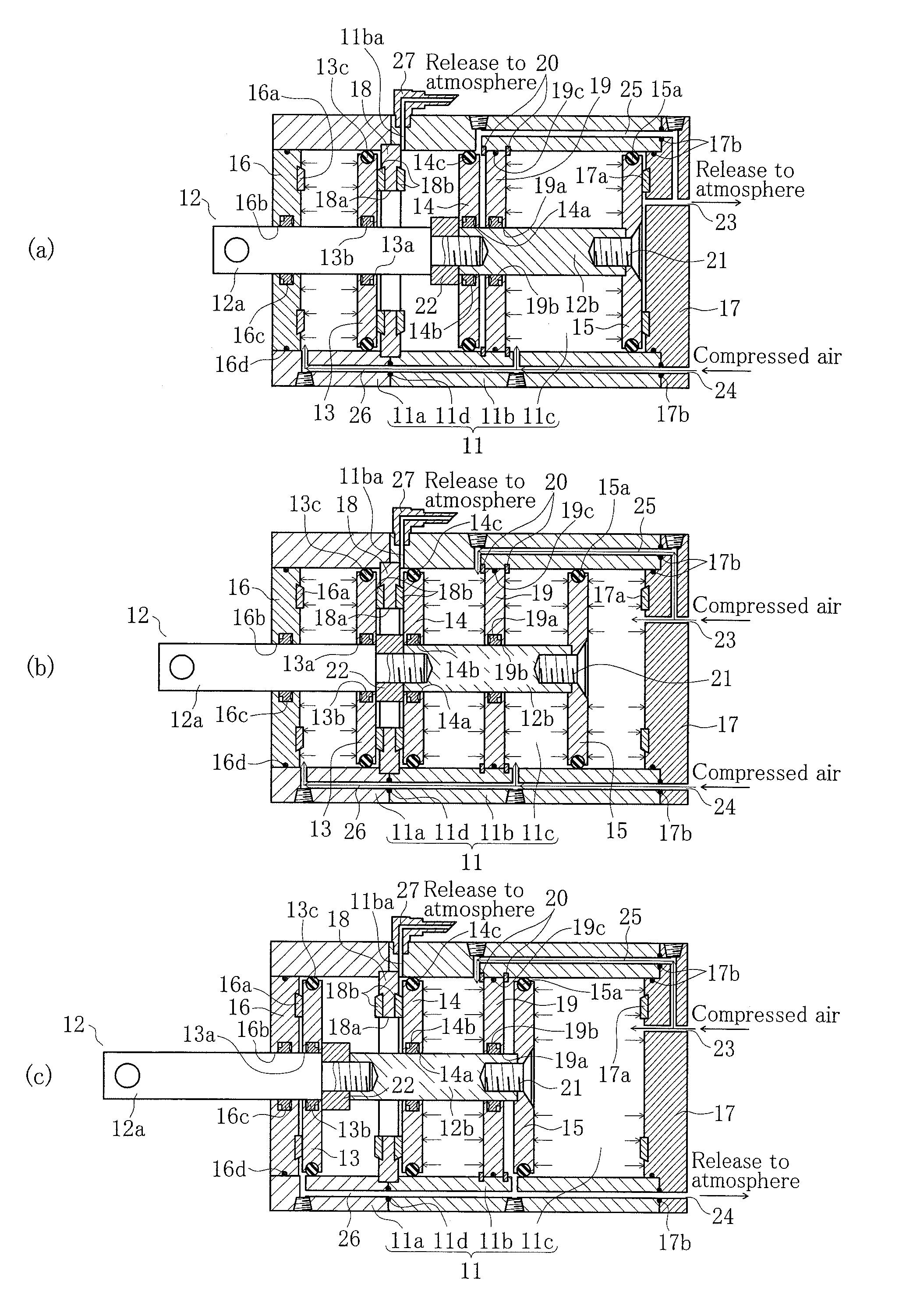
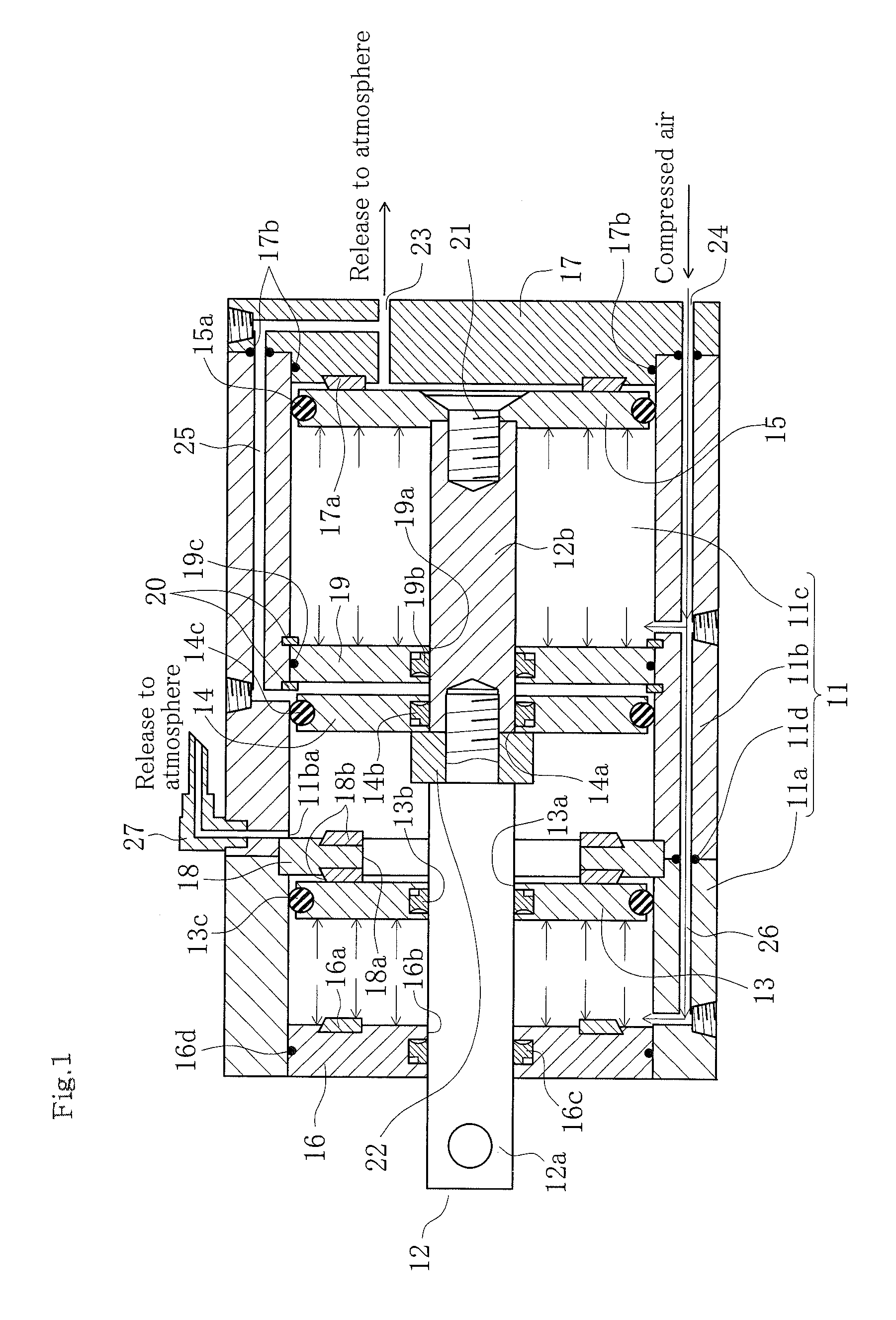
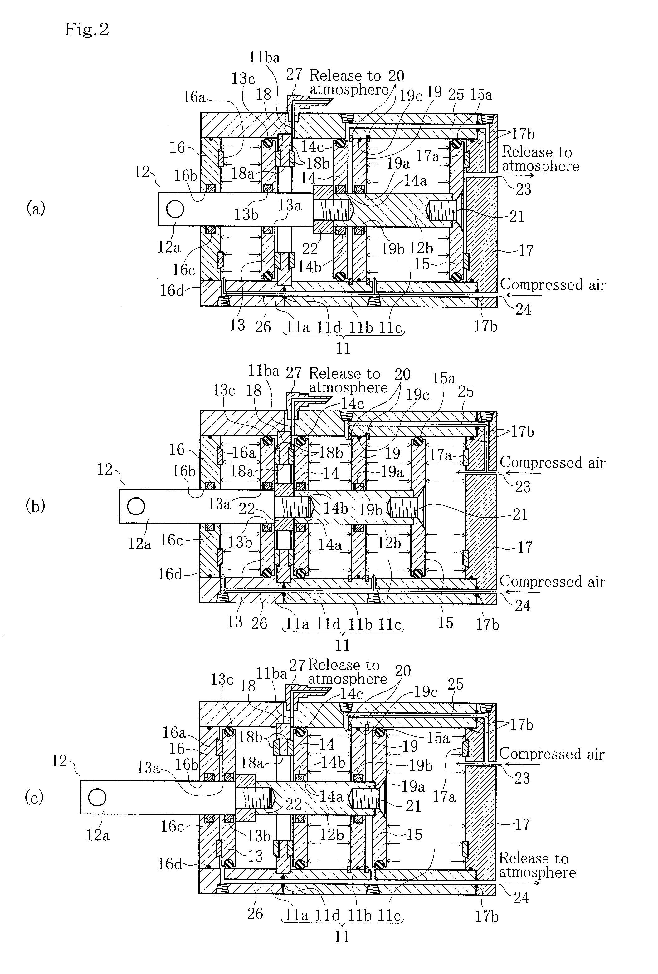
[0043]The 3-position operating actuator according to the present invention is described using FIG. 1 to FIG. 3 below. Following that, there is a description of an example of a permanent-magnet eddy-current deceleration device using this 3-position operating actuator as an actuator of a braking ON-OFF switching device, making reference to FIG. 4 and FIG. 5.

[0044]FIG. 1 is a sectional view illustrating the 3-position operating actuator according to the present invention. FIG. 1 illustrates a structure whereby the tip end of a rod 12 determines the three positions of braking OFF, partial braking, and braking ON, according to the movements of the first piston 13, the second piston 14, and the third piston 15 provided to the rod 12 within a cylinder 11.

[0045]In the example shown in FIG. 1, the cylinder 11 has a structure in which a first cylinder section 11a at one end of the cylinder and a second cylinder section 11b at the other end of the cylinder are serially connected. In addition, ...


PUM


Abstract

A braking actuator uses a single cylinder without using a spring to achieve a 3-position operation. A partition plate and an intermediate check plate are affixed within a cylinder at suitable intervals in the axial direction. Inserted movably in the axial direction of the cylinder are a first piston disposed between a pressing lid and the intermediate check plate, a second piston disposed between the intermediate check plate and the partition plate, and a third piston disposed between the partition plate and a pressing lid. A rod which is axially movable within the cylinder has a base end attached to the third piston and a tip end which extends outside from the cylinder through the partition plate, the second piston, the intermediate check plate, the first piston, and the pressing lid. A stopper affixed to a middle portion of the rod moves the first piston or the second piston.

Description

TECHNICAL FIELD[0001]The present invention relates to a 3-position operating actuator which enables braking control in three positions, and a permanent-magnet eddy-current deceleration device equipped with this actuator.BACKGROUND ART[0002]In large vehicles such as buses and trucks, foot brakes (friction brakes) are used as principal brakes, and engine brakes or exhaust brakes are used as auxiliary brakes. In recent years, as the engines installed in vehicles have increasingly small displacement, the capacity of engine brakes and exhaust brakes has decreased, resulting in a greater number of cases in which auxiliary brakes have been enhanced by introducing eddy-current devices.[0003]Recently, many such eddy-current devices no longer require current to be applied when braking because they use a permanent magnet as a magnetic pole (e.g., Patent Reference 1). At present, many of these permanent-magnet eddy-current deceleration devices are of the single-row rotation type or the double-r...

Claims


Application Information

Patent Timeline
Patent Type & Authority Patents(United States)
IPC IPC(8): F15B15/26H02K49/04F16D65/16F15B15/14F15B11/12F16D63/00B60T13/74B60T13/58F15B15/20F16D121/04F16D121/20
CPCF15B15/1409B60T13/586B60T13/748F15B11/123F15B15/149F15B15/26F16D63/002F16D65/16H02K49/043F15B2015/206F16D2121/04F16D2121/20F15B15/14F15B15/20H02K49/10
Inventor YAMAGUCHI, HIROYUKIOKUDA, YOZOYANAGIDO, KOKENIMANISHI, KENJI
Owner NIPPON STEEL CORP
Features
  • R&D
  • Intellectual Property
  • Life Sciences
  • Materials
  • Tech Scout
  • Unparalleled Data Quality
  • Higher Quality Content
  • 60% Fewer Hallucinations
Learn More