Electrical connector and electrical connector assembled component

a technology of electrical connectors and components, applied in the direction of securing/insulating coupling contact members, coupling device connections, printed circuits, etc., can solve the problems of difficult to obtain sufficient floating, contact failure at the terminal, and strong counterforce of elastic displacemen

Active Publication Date: 2016-10-25
HIROSE ELECTRIC GROUP
View PDF16 Cites 9 Cited by
  • Summary
  • Abstract
  • Description
  • Claims
  • Application Information

AI Technical Summary

Benefits of technology

[0014]According to the first aspect of the present invention, in the electrical connector having the above-described configuration, the upper housing and the lower housing are movable at least in the terminal arrangement direction within the certain amounts. Further, the terminals are held in the terminal grooves of the upper housing and the lower housing only at the upper end sides and the lower end sides. Movements of the terminals are not restricted at the portions with the wide groove width, other than portions with the narrow groove width, where movements are restricted in the up-and-down direction. Therefore, even when the upper end side and the lower end side of each terminal moves in a terminal arrangement direction due to displacement of the upper and the lower housings in the terminal arrangement direction so as to be in a floating state, any portion thereof other than the one causes contact pressure by contacting with a mating terminal does not elastically deform due to the floating, and simply tilt. As a result, elastic displacement of the terminals for the floating is not necessary.
[0018]According to the third aspect of the present invention, the terminals at suitable positions in the terminal arrangement direction are the grounding terminals. Further, the upper grounding connection member and the lower grounding member, which extend in the terminal arrangement direction, are provided so as to be capable of tightly holding from above and from under and of sliding to contact with the shaft-like sliding contact sections of the grounding terminals. When viewed from the up-and-down direction, the grounding terminals and the upper and lower grounding connection members form lattice-like shielding structure. Accordingly, it is possible to allow relative movements of the upper and the lower housings in the terminal arrangement direction and to enable the floating of the grounding terminals in the terminal arrangement direction without elastic deformation in the direction.
[0020]According to a fourth aspect of the present invention, with the configuration described above, the upper and the lower grounding connection members can contact with the grounding terminals at the sliding contact sections of the grounding terminals under elastic pressure, which can securely maintain the contact.
[0022]According to a sixth aspect of the present invention, it is possible to assemble an electrical connector assembled component from the above-described electrical connector and the mating connectors. The electrical connector assembled component includes the electrical connector of the present invention and the mating connectors to fit and connect to the electrical connector. The electrical connector includes a pivot protrusion, whereby at least one of an upper surface of the upper housing and a lower surface of the lower housing contacts with corresponding bottom wall surface of the housing of the mating connector, at a center in the connector's width direction. In addition, there is formed a gap between the electrical connector and the side wall surfaces of the mating connectors in the width direction, so that the electrical connector can rotate around the axis extending in the terminal arrangement direction and tilt having the pivot protrusion as a fulcrum. According to the electrical connector assembled component, the electrical connector can tilt around the pivot protrusion relative to the mating connectors.
[0023]As described above, according to the present invention, the upper end sides and the lower end sides of the terminals are accommodated in the terminal grooves of the upper housing and the lower housing, which are split into an upper piece and a lower piece, as the supporting positions. Further, the upper and the lower housings support the terminals in the terminal arrangement direction in the terminal grooves having the narrow groove width, and the terminal grooves have the wider width in areas other than the supporting positions on the upper end side and the lower end side. Therefore, even when the upper and the lower housings move relative to each other in the terminal arrangement direction, the terminals only tilt, and the elastic displacement is not generated for the relative movement. Accordingly, the terminals can have short arms, which can generate the minimum elastic displacement necessary for the arms to secure the contact pressure, thereby obtaining mechanical and electrical benefits.

Problems solved by technology

In this case, all the terminals may not always contact and connect to mating terminals at normal positions due to manufacturing errors and mounting / attaching errors, and the terminals could be off from their normal positions.
According to the conventional electrical connector disclosed in Patent Reference, however, there are mechanical and electrical issues due to generation of additional elastic displacement on the terminals so as to be capable of adding elastic displacement necessary for obtaining the contact pressure with the mating terminals and enabling the floating of the conventional electrical connector.
First, as the mechanical issues, in case of a connector in which a number of terminals are arranged, in order to enable the floating so as to absorb the displacement, if the terminals are elastically displaced, the counterforce by the elastic displacement tends to be strong since the total number of the terminals is large.
Accordingly, it is difficult to obtain the floating to a sufficient extent in some cases.
As a result, contact failure may occur at the terminals.
The electrical issues include deterioration of high-speed transmission characteristics.
Accordingly, the signal transmission length tends to become long, which in turn may cause deterioration of the high-speed transmission characteristics.

Method used


Image

  • Electrical connector and electrical connector assembled component
  • Electrical connector and electrical connector assembled component
  • Electrical connector and electrical connector assembled component

Examples


first embodiment

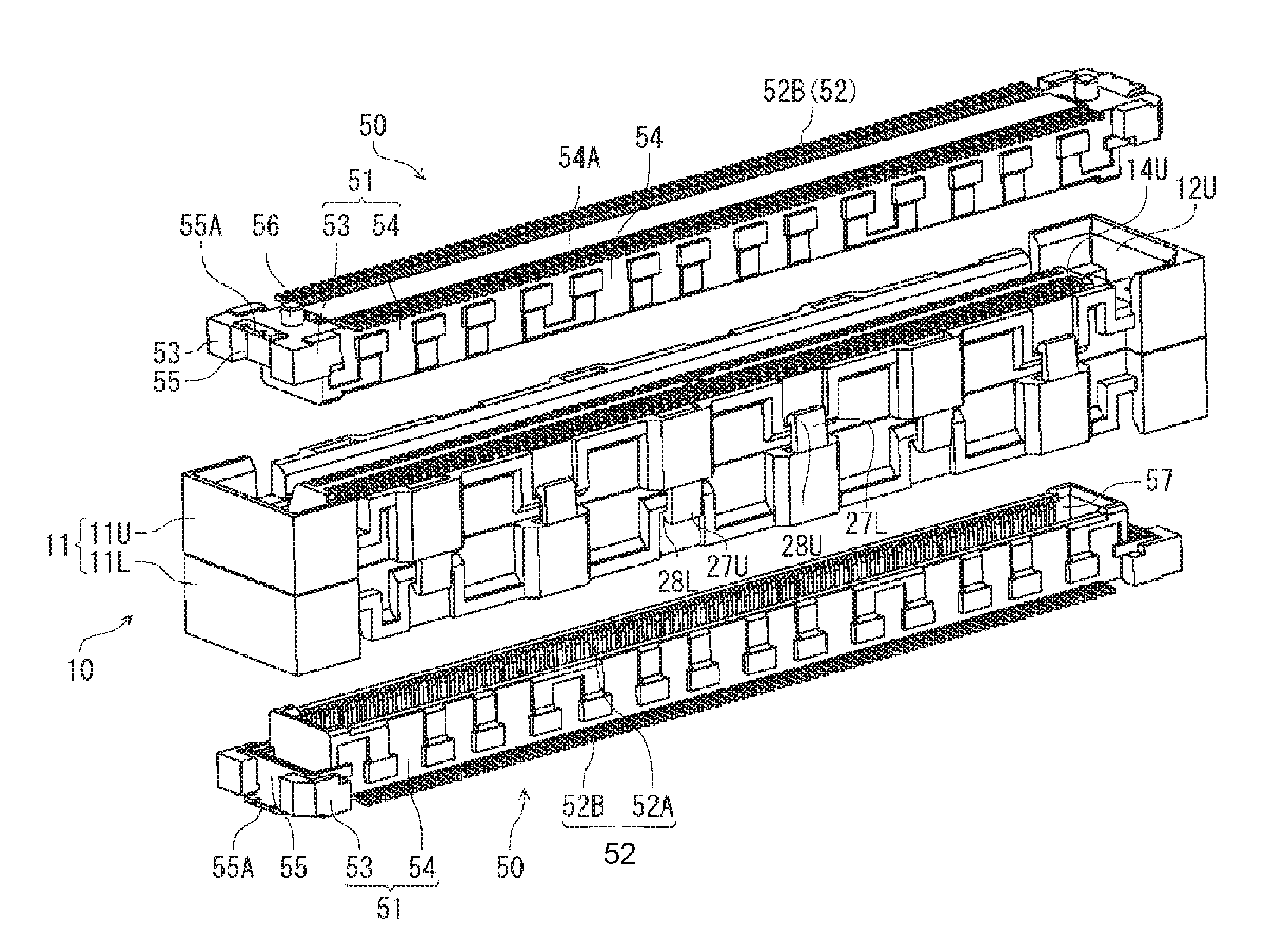
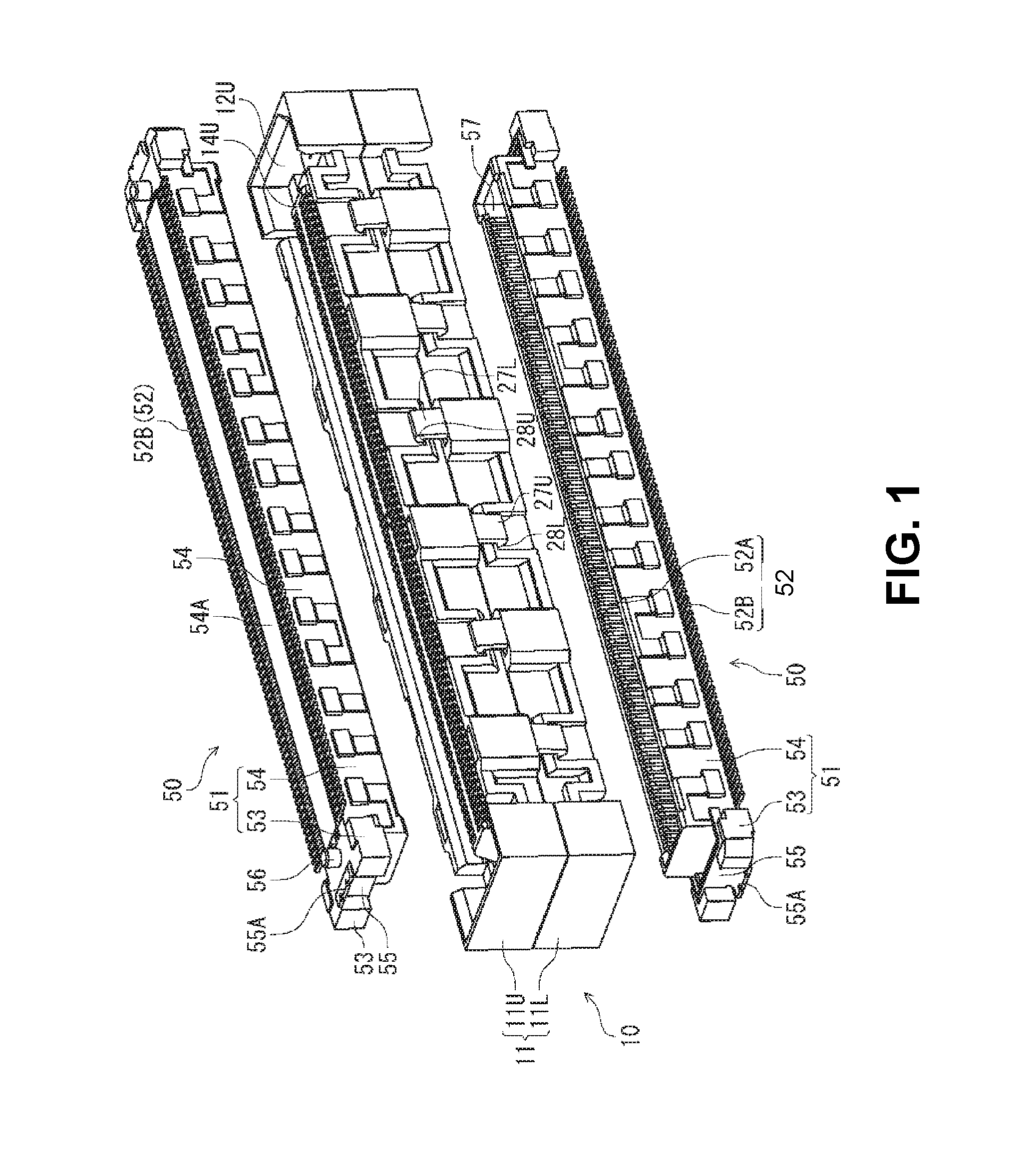
[0037]A first embodiment of the present invention will be explained. FIG. 1 is a perspective view showing outer appearance of the electrical connector assembled component formed of an electrical connector of the present invention and two mating connectors, right before assembling.

[0038]In the electrical connector assembled component of FIG. 1, two mating connectors 50 having the same configuration are disposed above and below an electrical connector 10 of this embodiment before fitting those mating connectors 50 to the electrical connector 10 for assembling, in which one of the mating connectors 50 is flipped upside down relative to the other. Then, the mating connectors 50 are fitted to the electrical connector 10 from thereabove and from thereunder for the assembling.

[0039]In the embodiment, as shown in FIG. 1, the mating connectors 50 have a same configuration and are to be fitted to the connector 10 while the mating connectors 50 are respectively mounted on circuit boards (not i...

second embodiment

[0091]A second embodiment of the present invention will be explained next. The first embodiment shown in FIGS. 1-9 and described above can be altered, modified, and changed. For example, it is possible to form the grounding connection members 40 as generally plate-like members and function as grounding plates. The grounding connection members 40 shown in FIG. 10 include the upper and the lower grounding members 40U and 40L, but also in this case, the upper and the lower grounding connection members 40U and 40L have the same configuration and are disposed simply flipping one of them upside down relative to the other as shown in FIG. 10(A). Therefore, the embodiment will be described referring to the upper grounding connection member 40U.

[0092]An upper edge of the upper grounding connection member 40U includes a flat strip-like section to be held 41U that extends in the connector's longitudinal direction, and a thin elastic sections 42U that extend diagonally from an upper edge of the...

third embodiment

[0096]A third embodiment of the present invention will be explained next. Not only in an intermediate connector for connecting the upper and lower mating connector as shown in those figures, it is also possible to apply the present invention in other types of intermediate connectors, for example the one, in which the mating connectors are disposed being capable of inserting / removing in perpendicular direction.

[0097]For example, in FIG. 11, the connector 10 that functions as an intermediate connector includes the lower housing 11L to fit the lower mating connector 50 from thereunder, and the upper housing 11U for fitting the upper mating connector 50 in the lateral direction (from the right side in the figure). The upper housing 11U is joined to the lower housing 11L from thereabove. In other words, the splitting surface where the upper housing 11U and the lower housing 11L contact by surface is in a horizontal direction, and although the position of the splitting surface is the same...


PUM


Abstract

An electrical connector is to be connected to a first mating connector and a second mating connector. The electrical connector includes a plurality of terminals; and a housing for holing the terminals in a terminal arrangement direction. The housing includes an upper housing and a lower housing attached to the upper housing. The upper housing includes a plurality of upper grooves for holding the terminals. Each of the upper grooves has an upper narrow width portion having a width smaller than other part of the upper groove. The lower housing includes a plurality of lower grooves for holing the terminal. Each of the lower grooves has a lower narrow width portion having a width smaller than other part of the lower groove.

Description

BACKGROUND OF THE INVENTION AND RELATED ART STATEMENT[0001]The present invention relates to an electrical connector, and an electrical connector assembled component that includes the electrical connector and a mating connector thereof. More specifically, the present invention relates to an electrical connector having a terminal configured so that a contact portion of the terminal contacting with a mating terminal of a mating connector is capable of shifting within a specific amount, and to an electrical connector assembled component that includes the electrical connector and a mating connector thereof.[0002]A conventional electrical connector of this type has been disclosed in, for example, Patent reference. The conventional electrical connector includes male terminals made through punching a sheet metal in a sheet thickness direction. The male terminals have a shape of a transverse S-character, in which a U-shape section thereof is connected to an inverse U-shaped section thereof. ...

Claims


Application Information

Patent Timeline
Patent Type & Authority Patents(United States)
IPC IPC(8): H01R12/00H05K1/00H01R13/506H01R12/91H01R13/42H01R12/71H01R13/6585H01R12/73H01R12/70
CPCH01R13/42H01R12/712H01R12/91H01R13/506H01R13/6585H01R12/7082H01R12/73
Inventor OSHIDA, TADASHI
Owner HIROSE ELECTRIC GROUP
Why Eureka
Try Eureka