Locking mechanism for plug-in connectors

a plug-in connector and locking mechanism technology, which is applied in the direction of electrical apparatus, connection, coupling device connection, etc., can solve the problems of inability to ensure the complete latching the latching means of the plug-in connector is constantly acted on, and the latching means are easily worn and deteriorated

Active Publication Date: 2016-10-25
HARTING ELECTRIC GMBH & CO KG
View PDF21 Cites 5 Cited by
  • Summary
  • Abstract
  • Description
  • Claims
  • Application Information

AI Technical Summary

Benefits of technology

[0011]It is the object of the invention to provide a locking mechanism for plug-in connectors, which ensures a complete latching and indicates this to the user in a clear manner. Moreover, the locking mechanism should be suitable for a large number of plug-in cycles, without there being any risk of wear and tear, above all on the latching means.
[0020]In an advantageous embodiment of the Invention, the primary locking element is implemented as a rocker-type component which is rotationally supported in a base body of the locking mechanism via an Integral rotary axis. In this way, the mating connector can be locked or released by tilting the primary locking element.

Problems solved by technology

A disadvantageous effect of the solutions known from the prior art is that a force constantly acts onto the latching means of the plug-in connectors.
This greatly increased force leads, in the case of frequent unlocking actions of the plug-in connectors, to rapid wear and tear of the latching means.
Another negative effect of the devices known from the prior art is that a complete latching of the plug-in connectors cannot always be ensured.
In the case of very great plug-in and / or contacting forces of the internal contacts of the plug-in connectors, incomplete latching as a result of the high friction of the latching means may be caused.

Method used


Image

  • Locking mechanism for plug-in connectors
  • Locking mechanism for plug-in connectors
  • Locking mechanism for plug-in connectors

Examples


Embodiment Construction

[0032]An embodiment example of the invention is shown in the drawings and will be explained in more detail below, wherein:

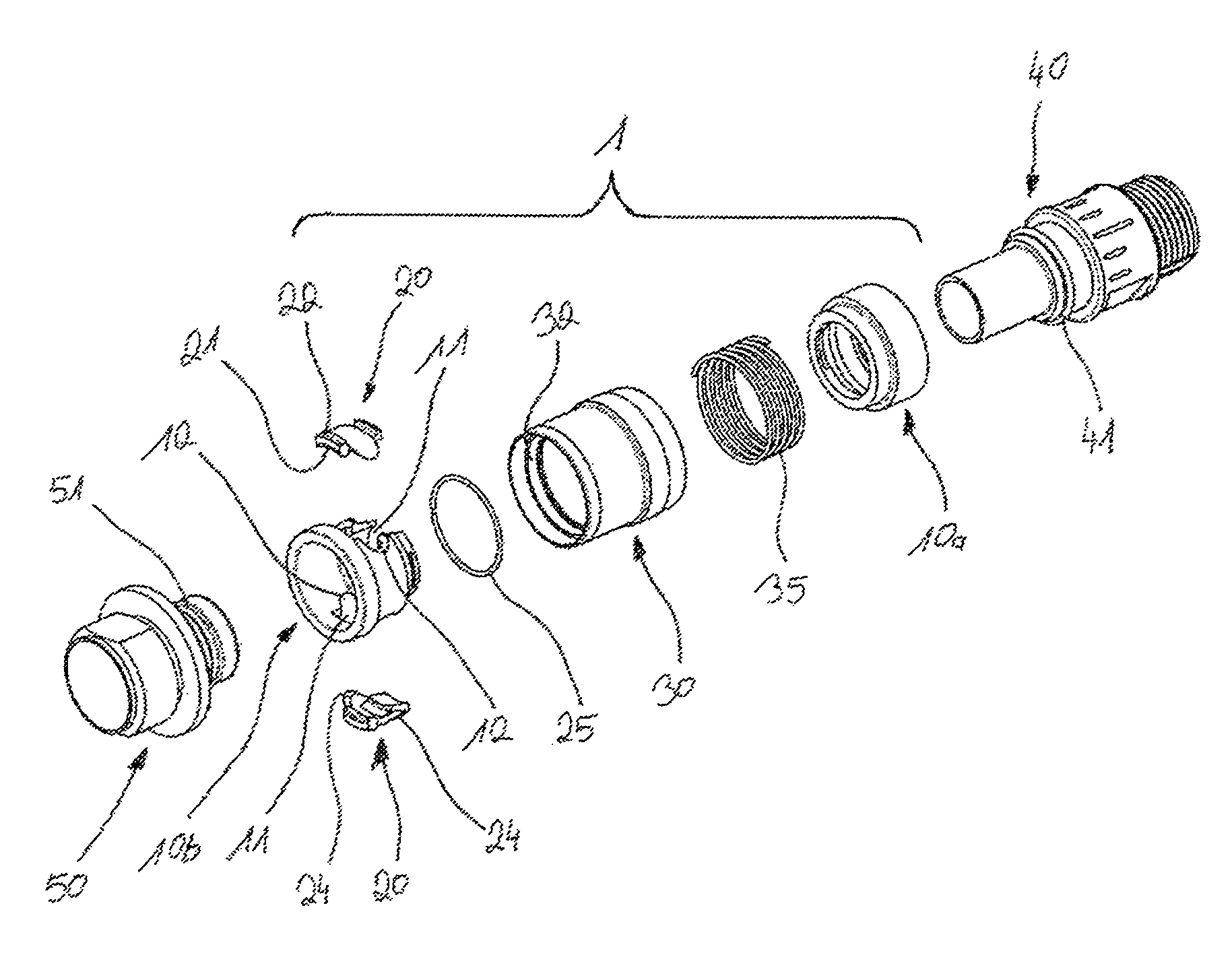
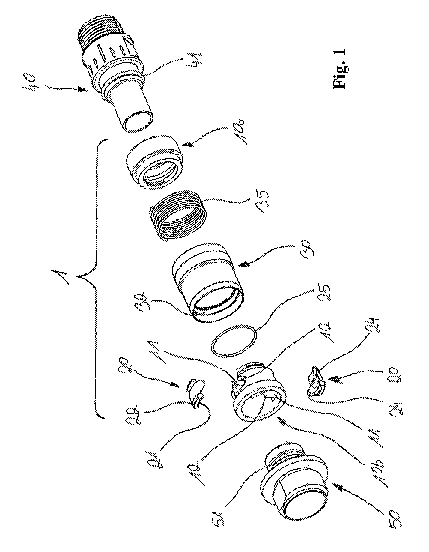
[0033]FIG. 1 shows a perspective exploded view of a locking mechanism according to the invention with a plug-in connector and a mating connector;

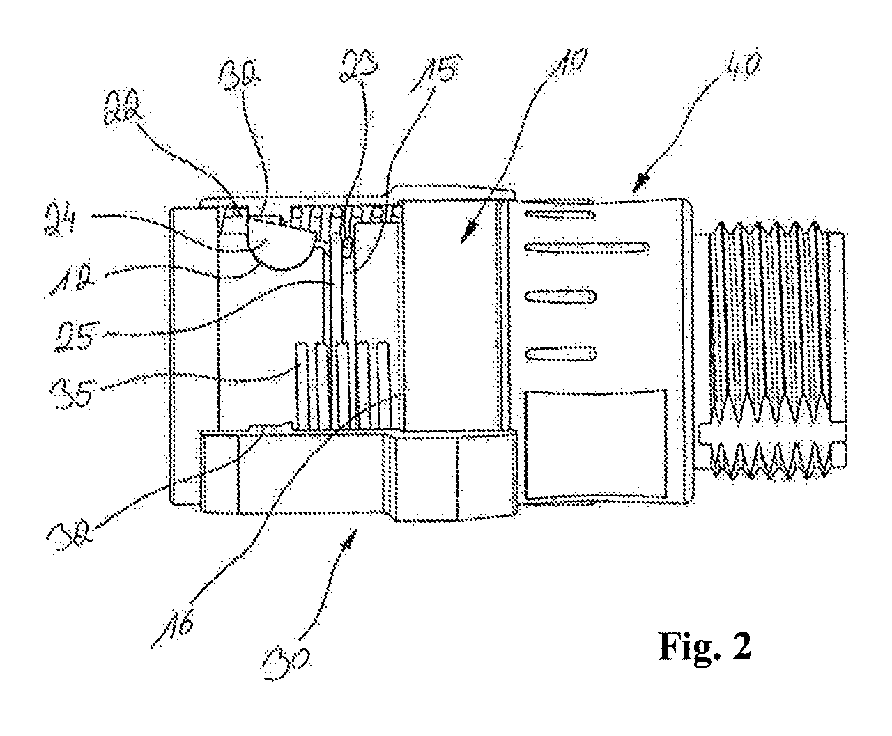
[0034]FIG. 2 shows the locking mechanism according to the invention in a partially sectioned view;

[0035]FIG. 3 shows a section through a locking mechanism in an opened state;

[0036]FIG. 4 shows a section as in FIG. 3 with a mating connector in a partially contacted state;

[0037]FIG. 5 shows a section as in FIG. 4 in a fully contacted, closed, non-locked state; and

[0038]FIG. 6 shows a sectional view through the locking mechanism in the fully contacted and locked state.

[0039]FIG. 1 shows a locking mechanism 1 according to the invention in a three-dimensional exploded view. Moreover, a plug-in connector 40 is shown on which the locking mechanism 1 can in this embodiment be fastened by means of a snap ring 41. On the opposite ...


PUM


Abstract

The invention relates to a locking mechanism for plug-in connectors with a mating connector. Such a locking mechanism has two types of locking means, a primary locking element that is suitable for locking the mating connector and a secondary locking element that is suitable for mutually locking with the primary locking element. In doing so, the secondary locking element locks the primary one in the locked state of the locking mechanism and the primary locking element locks the secondary one in the unlocked state. By contacting the mating connector, the mechanism is automatically locked and is unlocked by actuating the secondary locking element which is implemented as an actuator.

Description

[0001]The invention relates to a locking mechanism for locking a plug-in connector with a mating connector.[0002]Such locking mechanisms are needed in order to achieve a secure mechanical, non-permanent connection of the plug-in connector with the mating connector. To this end it has to be ensured that in the contacted state, both plug-in connectors are mechanically completely latched together and also that the internal contacts are completely connected.[0003]The category of plug-in connectors may relate to both electrical and optical, pneumatic or hydraulic plug-in connectors. Such locking mechanisms may be applied to any desired type of plug-in connectors.[0004]Apart from the mechanical connection of the plug-in connectors, also the release of the connection has to be ensured. To this end, the mechanical latching has to be completely released, without in doing so destroying components of the locking mechanism or of the plug-in connectors.[0005]It has to be possible for these conta...

Claims


Application Information

Patent Timeline
Patent Type & Authority Patents(United States)
IPC IPC(8): H01R4/50H01R13/627H01R13/639
CPCH01R13/639H01R13/627
Inventor FRIESEN, HEINRICH
Owner HARTING ELECTRIC GMBH & CO KG
Why Eureka
Try Eureka