Fabrication and Harvest of Piezoelectric Plates

a piezoelectric plate and fabrication technology, applied in the direction of piezoelectric/electrostrictive/magnetostrictive devices, basic electric elements, electrical equipment, etc., can solve the problems of limiting the sensitivity of the ultrasonic sensor array, limiting the use of such a structure, and high sintering temperature incompatible with the formation of such materials

Active Publication Date: 2017-12-07
ELUX INC
View PDF2 Cites 3 Cited by
  • Summary
  • Abstract
  • Description
  • Claims
  • Application Information

AI Technical Summary

Benefits of technology

[0006]Disclosed herein are a structure and method for fabricating disks formed from lead zirconate titanate (PZT) or other piezoelectric materials that ensures completion of all high-temperature processing of the piezoelectric ceramic prior to harvesting from a growth substrate. The piezoelectric disks can then be used in a variety of applications such as an ultrasonic sensor array for a touchscreen or imaging sensor, structural or personal health monitor, or a ferroelectric memory array.
[0007]PZT disks can be formed on a growth substrate in a variety of ways, including the molding of a sol-gel PZT precursor or chemical solution deposition of sol-gel PZT. By forming the disks on a separate growth substrate, the sintering process can be carried out using optimized conditions for forming the PZT material (e.g., sintering at 650° C. for several hours). The disks can be formed on the growth substrate with top and bottom metal electrodes for low contact resistance.

Problems solved by technology

However, the formation of such materials typically requires high sintering temperatures that are incompatible with low-cost, high-temperature-intolerant substrates such as glasses or plastics.
However, the piezoelectric coefficient of these polymer materials is typically 25 times lower than that for the ceramic piezoelectric materials, thereby limiting the sensitivity of the ultrasonic sensor array.
There is a very limited use for such a structure.
Further, there has been no means demonstrated for separating these disks from the growth substrate, forming the disks into individual electrical devices, or a particular use shown for individual disk electrical devices.

Method used


Image

  • Fabrication and Harvest of Piezoelectric Plates
  • Fabrication and Harvest of Piezoelectric Plates
  • Fabrication and Harvest of Piezoelectric Plates

Examples


Embodiment Construction

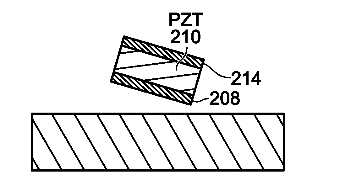
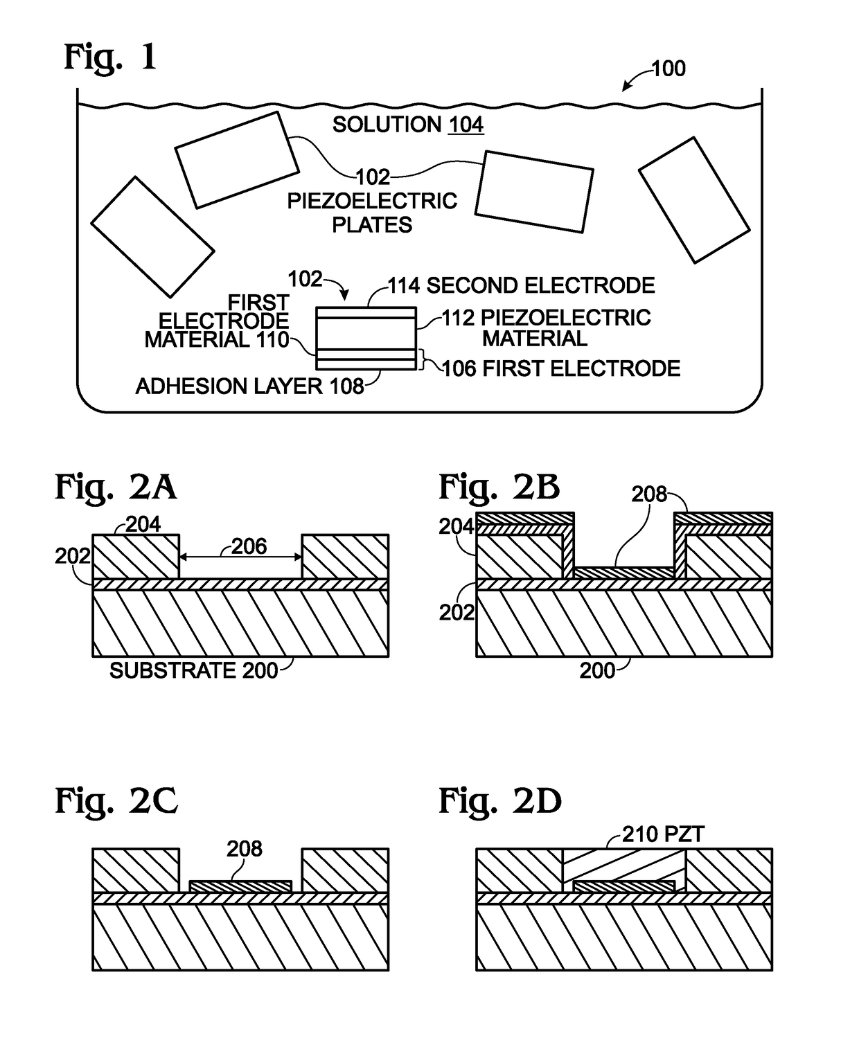
[0014]FIG. 1 is a partial cross-sectional view of a fluidic assembly solution 100 of piezoelectric plates. A plurality of piezoelectric plates 102 are suspended in a solution 104. Each plate 102 comprises a planar first electrode 106 having an adhesion layer 108 / first electrode material 110 stack. A piezoelectric material 112 overlies the first electrode material 110, and a planar second electrode 114 overlies the piezoelectric material. For clarity, only one piezoelectric plate is shown in detail. Note: the second electrode is not necessarily a “top” electrode, as the plates are not aligned in any particular manner when in solution.

[0015]The piezoelectric material 112 may be one of the following: lead zirconium titanate (PZT), barium titanate (BaTiO3), polyvinylidene fluoride (PVDF), polyvinylidene fluoride co-polymers (P(VDF-TrFE), quartz, zinc oxide (ZnO), aluminum nitride (AlN), or lanthanum-doped lead zirconium titanate (PZLT). However, the piezoelectric plates are not limited ...


PUM


Abstract

A method is provided for fabricating piezoelectric plates. A sacrificial layer is formed overlying a growth substrate. A template layer, with openings exposing sacrificial layer surfaces, is formed over the sacrificial layer. An adhesion layer / first electrode stack is selectively deposited in the openings overlying the sacrificial layer surfaces, and a piezoelectric material formed in the openings overlying the stack. Then, a second electrode is formed overlying the piezoelectric material. Using the second electrode as a hardmask, the piezoelectric material is etched to form polygon-shaped structures, such as disks, attached to the sacrificial layer surfaces. After removing the template layer and annealing, the polygon-shaped structures are separated from the sacrificial layer. With the proper choice of growth substrate material, the annealing can be performed at a relatively high temperature.

Description

BACKGROUND OF THE INVENTION1. Field of the Invention[0001]This invention generally relates to thin-film device fabrication and, more particularly, to the fabrication of piezoelectric structures requiring high temperature annealing.2. Description of the Related Art[0002]Ceramic piezoelectric materials such as lead zirconate titanate (PZT) or barium titanate (BaTiO3) have a high piezoelectric coefficient that allows for their use in high-sensitivity ultrasonic sensors or energy harvesters. However, the formation of such materials typically requires high sintering temperatures that are incompatible with low-cost, high-temperature-intolerant substrates such as glasses or plastics.[0003]Currently, this problem can be addressed using a polymer-based piezoelectric material, such as polyvinylidene fluoride (PVDF) or polyvinylidene fluoride co-polymer (P(VDF-TrFE), that can be spin-coated onto the receiving substrate. However, the piezoelectric coefficient of these polymer materials is typic...

Claims


Application Information

Patent Timeline
Patent Type & Authority Applications(United States)
IPC IPC(8): H01L41/332H01L41/314H01L41/297H01L41/187H01L41/193
CPCH01L41/332H01L41/314H01L41/297H01L41/1873H01L41/1871H01L41/193H01L41/1876H10N30/8536H10N30/8554H10N30/857H10N30/081H10N30/082H10N30/067H10N30/074H10N30/8542
Inventor CROWDER, MARK ALBERTZHAN, CHANGQINGNISHIMURA, KARENSCHUELE, PAUL
Owner ELUX INC
Why Eureka
Try Eureka