Disk drive and tray control mechanism

a control mechanism and disk drive technology, applied in the direction of record information storage, record carrier contruction details, instruments, etc., can solve the problems of undesired tray blockage, increase the starting torque, improve the performance of the disk drive, and increase the resistance of electric motors

Inactive Publication Date: 2010-06-10
MMD HONG KONG HLDG LTD
View PDF6 Cites 5 Cited by
  • Summary
  • Abstract
  • Description
  • Claims
  • Application Information

AI Technical Summary

Benefits of technology

[0007]In a still further embodiment, the tray-out command and the tray-in command is initiated using the normal operating voltage of the tray motor upon completing the pulsation of the tray motor. This is carried out to ensure that the contamination of the tray motor is removed and to check that the tray can be operated with normal operating voltage. This ensures the completion of the tray block cleaning process.
[0008]In a still further embodiment, a tray motor drive voltage is determined while the tray is in the intermediate position upon initiating the tray-out command or the tray-in command. The pulsating voltage for pulsating the tray motor is selected based on the maximum tray motor driving voltage allowable by the disk drive. This has the advantage that it is sufficient to overcome the increased starting torque that is needed to drive the tray motor due to the increased electric motor resistance when the tray motor is contaminated.
[0009]In a still further embodiment, the number of pulses required to rectify the tray block is counted. The tray motor is pulsated using a pulsating voltage that is a function of the counted number of pulses. The method automatically determines the number of times the tray motor clean process has to be triggered, rectifies tray blockage and thereby improves disk drive performance.

Problems solved by technology

This kind of tray blockage is undesired, especially in audio / video disk drives.

Method used


Image

  • Disk drive and tray control mechanism
  • Disk drive and tray control mechanism
  • Disk drive and tray control mechanism

Examples


Embodiment Construction

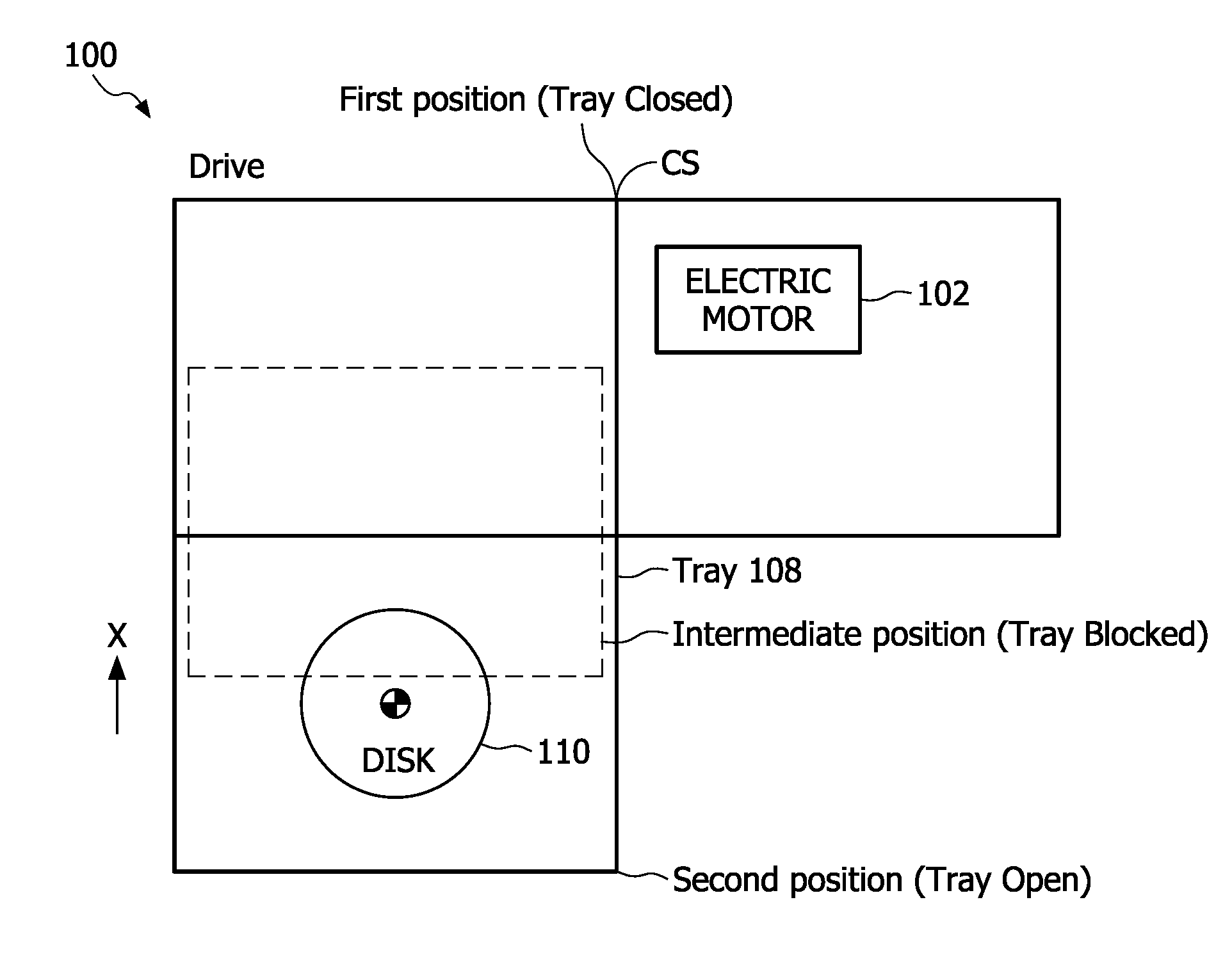
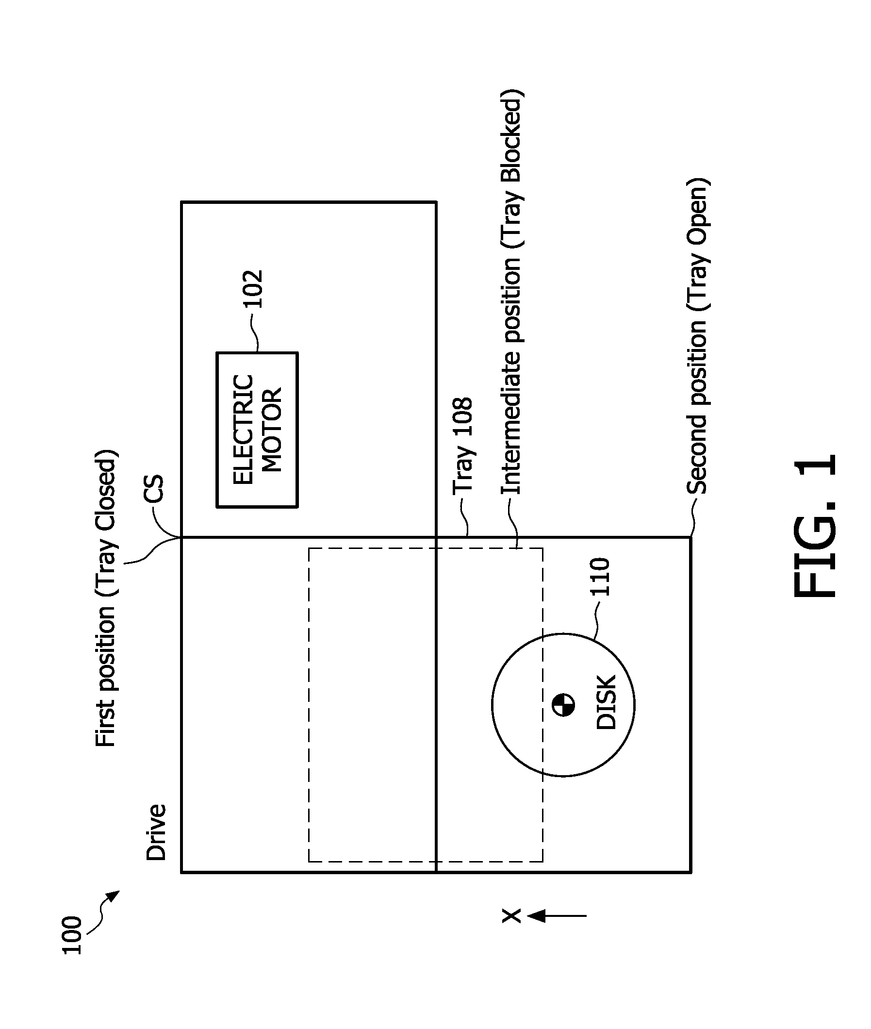
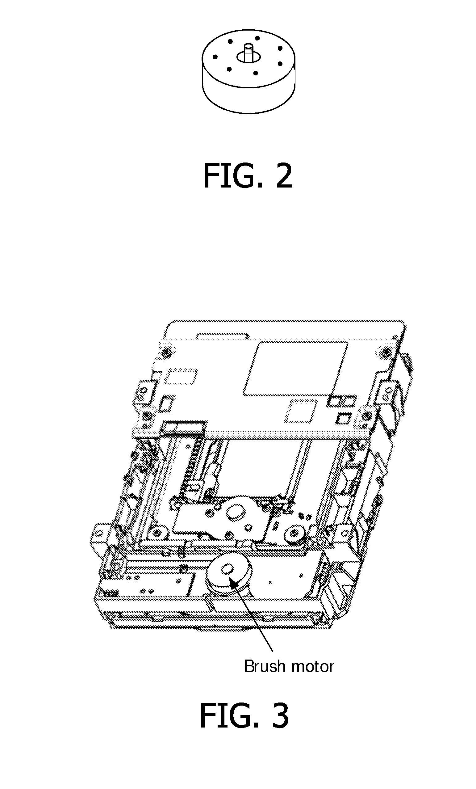
[0025]Accordingly, a method of automatically detecting and rectifying the tray block is disclosed. The method detects the occurrence of the tray block in the disk drive upon receiving a tray-out command or a tray-in command by determining whether the tray is in an intermediate position for a predetermined time period, the intermediate position being a position between a first position within a casing of the disk drive and a second position projecting completely outwards from the casing, the tray arranged to receive a record carrier when in the second position and being supported for movement between the first position and the second position. Based on the outcome of the detection, the tray block is rectified by cleaning a brush-commutator interface of a tray motor, the tray motor arranged to move the tray between the first position and the second position.

[0026]When the tray is in open position (Cf. FIG. 1 Tray Open) and the tray is to be closed, the tray-in command is initiated. Th...


PUM

PropertyMeasurementUnit
time periodaaaaaaaaaa
pulsating voltageaaaaaaaaaa

Abstract

A method (1000) to automatically detect and rectify a tray block in a disk drive (100) is disclosed. The method comprises detecting an occurrence of a tray block in a disk drive (100) upon receiving a tray-out command or a tray-in command by determining whether the tray (108) is in an intermediate position for a predetermined time period, the intermediate 5 position being a position between a first position within a casing of the disk drive (100) and a second position projecting completely outwards from the casing, the tray arranged to receive a record carrier (110) when in the second position and being supported for movement between the first position and the second position. The detected tray block is rectified by cleaning a brush-commutator interface of a tray motor (102), the tray motor being arranged to 10 move the tray (108) between the first position and the second position. The technique is useful for CD, DVD and BD recorders and for players which have the design of tray open/close mechanism.

Description

FIELD OF THE INVENTION[0001]The subject matter relates in general to disk drives, and more specifically to tray control mechanism of a disk drive.BACKGROUND OF THE INVENTION[0002]WO 2005 / 001827 discloses a disk drive comprising a tray for receiving a disk, the tray being supported for movement between a first position within a casing of the disk drive and a second position projecting from the casing, an electric motor for moving the tray between the first position and the second position, and regulation means for regulating an electric current through the electric motor for regulating the rotation of the electric motor. In such disk drives during the opening of the tray or during the closing of the tray, the tray can sometimes get blocked. The term tray block means the tray is neither in the closed position nor in the open position. The tray is struck in an intermediate position. This kind of tray blockage is undesired, especially in audio / video disk drives.[0003]It is therefore an ...

Claims


Application Information

Patent Timeline
Patent Type & Authority Applications(United States)
IPC IPC(8): G11B17/04H02K13/12
CPCG11B17/056G11B17/047G11B17/04H02K13/12
Inventor LOH, KUM CHUNGZHOU, YU
Owner MMD HONG KONG HLDG LTD
Why Eureka
Try Eureka