Spinal alignment frame

a technology of spine and frame, applied in the direction of internal osteosythesis, internal osteosythesis, osteosythesis devices, etc., can solve the problems of rod housings moving relative to each other, and affecting the function of the spin

Active Publication Date: 2016-11-01
NUVASIVE
View PDF13 Cites 21 Cited by
  • Summary
  • Abstract
  • Description
  • Claims
  • Application Information

AI Technical Summary

Problems solved by technology

Even slight disruptions to either the intervertebral discs or vertebrae can result in serious discomfort due to compression of nerve fibers either within the spinal cord or extending from the spinal cord.
If a disruption to the spine becomes severe enough, damage to a nerve or part of the spinal cord may occur and can result in partial to total loss of bodily functions (e.g., walking, talking, breathing, etc.).
This can be a challenge as it requires the rod channels of adjacent rod housings to be generally aligned, or alternatively, the rod must be bent to fit.
However, doing so typically causes the rod housings to move relative to each other.
Thus, achieving the desired correction (realignment) of the vertebrae while also aligning the rod channels of the housings to effectively seat a rod is a significant challenge and can create difficulties and delays during the surgery.

Method used


Image

  • Spinal alignment frame
  • Spinal alignment frame
  • Spinal alignment frame

Examples


Embodiment Construction

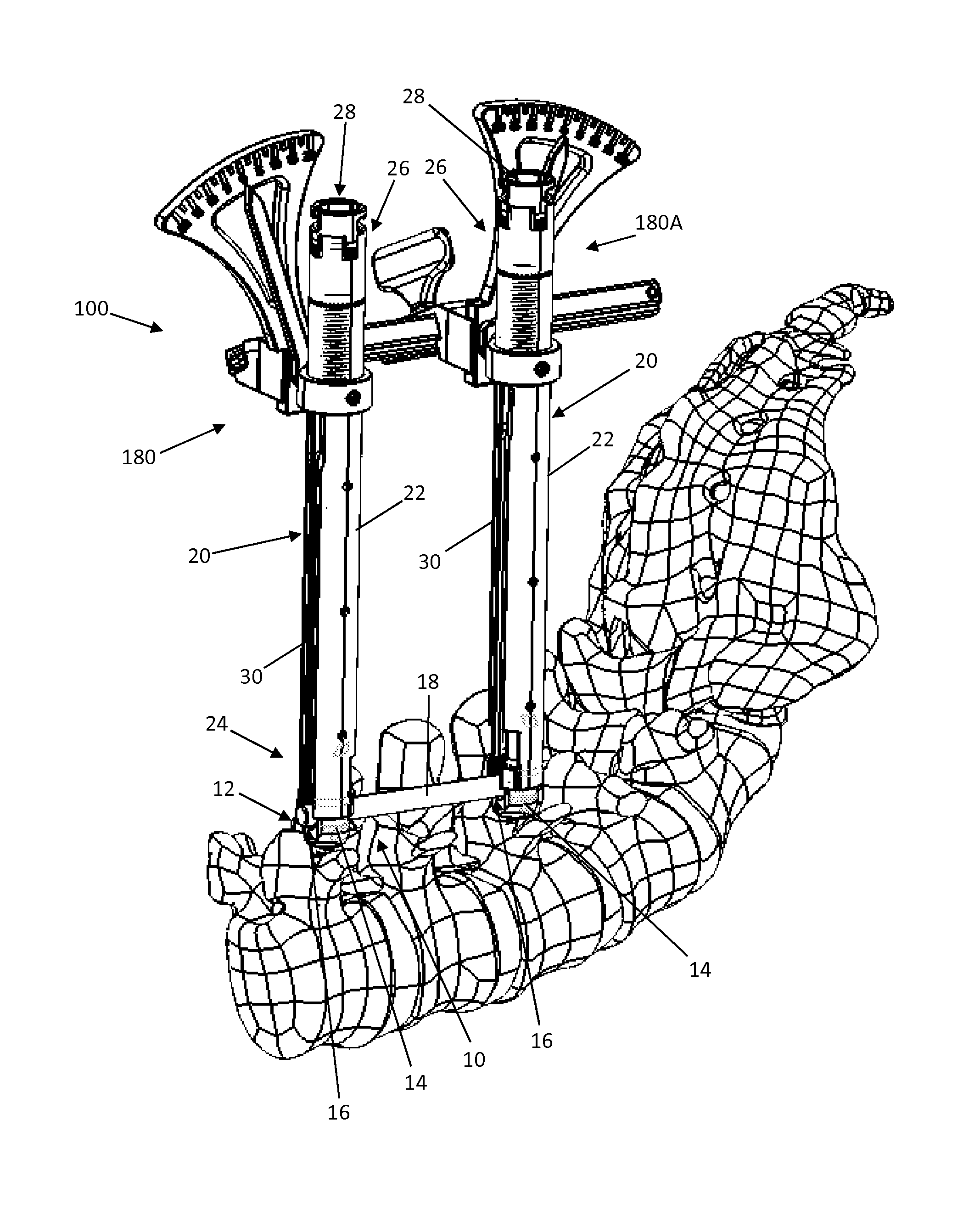
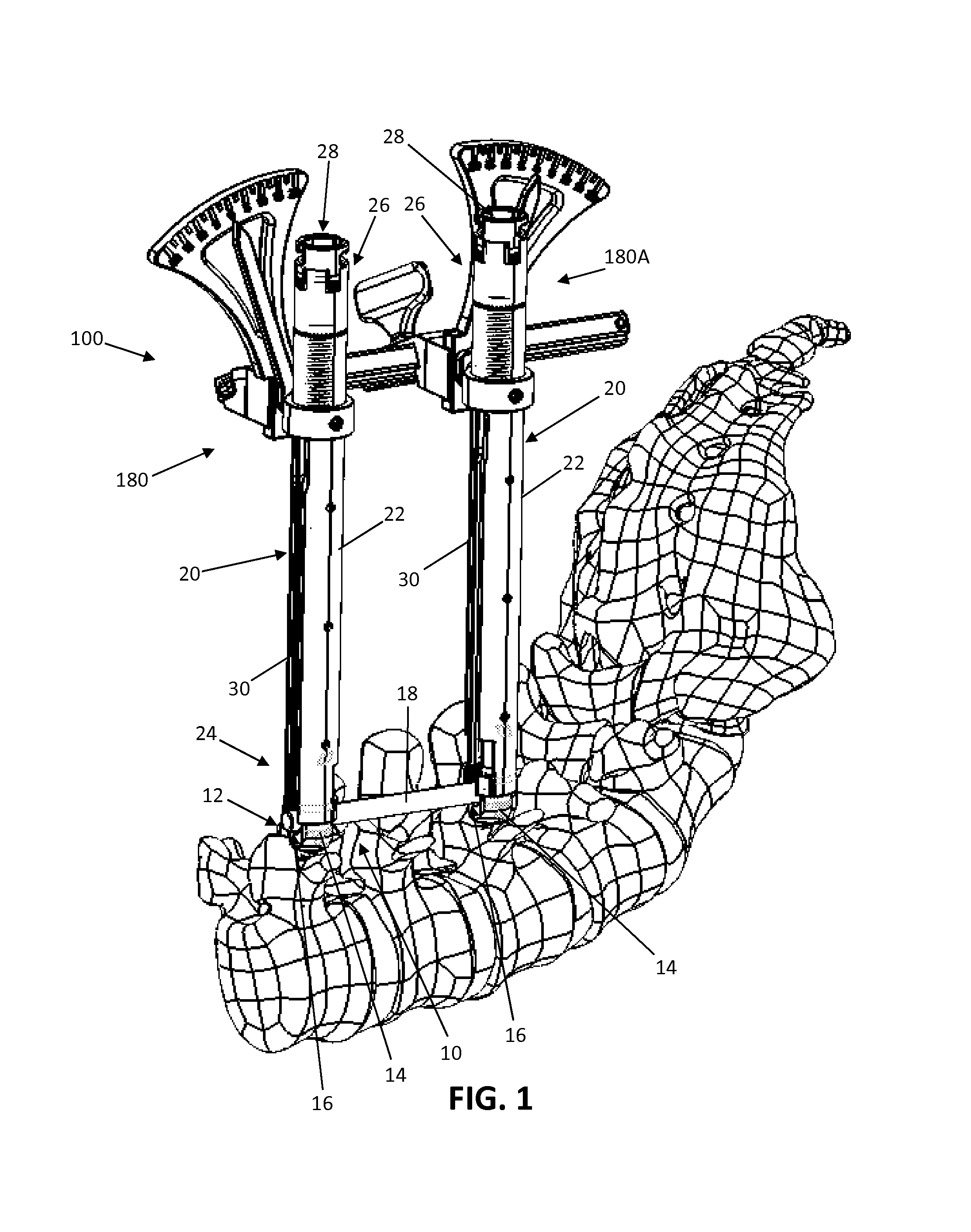
[0017]Various embodiments disclosed herein include surgical measurement frames that can be conveniently used by a surgeon to determine an appropriate surgical correction for a patient suffering from a spinal instability or deformity. For example, the surgical measurement frame may be used to realign sagittal balance during compression fracture reduction, VBR resection, pedicle subtraction osteotomy (PSO), scoliosis correction, or other procedures affecting sagittal balance.

[0018]With reference to FIG. 1, there is shown a spinal fixation construct 10 and associated installation guide assemblies 20, coupled with an example embodiment of a spinal alignment frame 100. The spinal fixation construct is of a type commonly known in the art and includes a pair of pedicle screws 12 and a rod 18. The pedicle screws 12 each include a rod housing 14 and a shank (not pictured) coupled to the housing. The housing 14 has pair of upstanding arms separated by a rod channel 16 in which the fixation ro...


PUM


Abstract

Disclosed is a surgical alignment and distraction frame and associated methods of use that facilitates correction of a sagittal imbalance. The alignment and distraction frame works in conjunction with pedicle screw installation guide assemblies to impart the desired correction. The alignment frame can be utilized to ensure the pedicle screw housings are aligned (to facilitate rod coupling) in concert with the completion of a correction maneuver.

Description

CROSS REFERENCES TO RELATED APPLICATIONS[0001]The present application is a non-provisional application claiming the benefit of priority under 35 U.S.C. §119(e) from commonly owned U.S. Provisional Application Ser. No. 61 / 794,723 filed on Mar. 15, 2013 and entitled “Spinal Alignment Frame,” the entire contents of which is hereby incorporated by reference into this disclosure as if set forth fully herein.FIELD[0002]The present invention relates to the field of spinal surgery and spinal fixation devices, including a system and associated methods for manipulating, distracting and / or reorienting vertebrae of the spine in conjunction with the installation of a spinal fixation construct.BACKGROUND[0003]The spine is formed of a column of vertebra that extends between the cranium and pelvis. The three major sections of the spine are known as the cervical, thoracic and lumbar regions. There are 7 cervical vertebrae, 12 thoracic vertebrae, and 5 lumbar vertebrae, with each of the 24 vertebrae ...

Claims


Application Information

Patent Timeline
Patent Type & Authority Patents(United States)
IPC IPC(8): A61B17/88A61B17/70
CPCA61B17/7083A61B17/7077A61B17/7035A61B17/7079A61B17/708A61B2017/681
Inventor SCHAFER, ANDREWGERMAN, ROBERTYOUSSEF, JIM A.LISH, SCOTTDOOSE, JUSTIN
Owner NUVASIVE
Why Eureka
Try Eureka