
Fitting for a vehicle seat and vehicle seat

a technology for vehicle seats and seats, applied in the direction of vehicle components, movable seats, vehicle arrangements, etc., can solve the problems of false assessment of fittings, difficult to detect whether the measured eccentric angle is still within the admissible eccentric angle defined by permitted component tolerances, and unsuitable opening of fittings, etc., to improve the fit, improve the fit, and optimize the effect of locking security

Active Publication Date: 2016-11-01
KEIPER SEATING MECHANISMS CO LTD
View PDF21 Cites 2 Cited by
  • Summary
  • Abstract
  • Description
  • Claims
  • Application Information

AI Technical Summary

Benefits of technology

[0008]An object of the invention is to improve a fitting of the type mentioned in the introduction, in particular to design said fitting so that it is less sensitive to tolerances. Secure locking is intended to be ensured even under unfavorable load conditions, and a simpler option is provided to assess the locked state of the fitting reliably using the eccentric angle. An object of the invention is to improve a vehicle seat by using a fitting with optimized locking security.

Problems solved by technology

Unfavorable load conditions, however, in particular cyclical or vibratory stresses, may lead under adverse conditions to an undesired rotation of the eccentric and as a result to an undesired opening of the fitting.
Known eccentrics have the drawback that it is difficult to detect whether the measured eccentric angle is still within an admissible eccentric angular range defined by permitted component tolerances.
Inaccuracies in terms of measurements and / or readings of the eccentric angle may lead to a false assessment of the fitting.
This small angle of rotation makes it complicated to assess the locked state of the fitting in a reliable manner by using the eccentric angle.

Method used


Image

  • Fitting for a vehicle seat and vehicle seat
  • Fitting for a vehicle seat and vehicle seat
  • Fitting for a vehicle seat and vehicle seat

Examples


Embodiment Construction

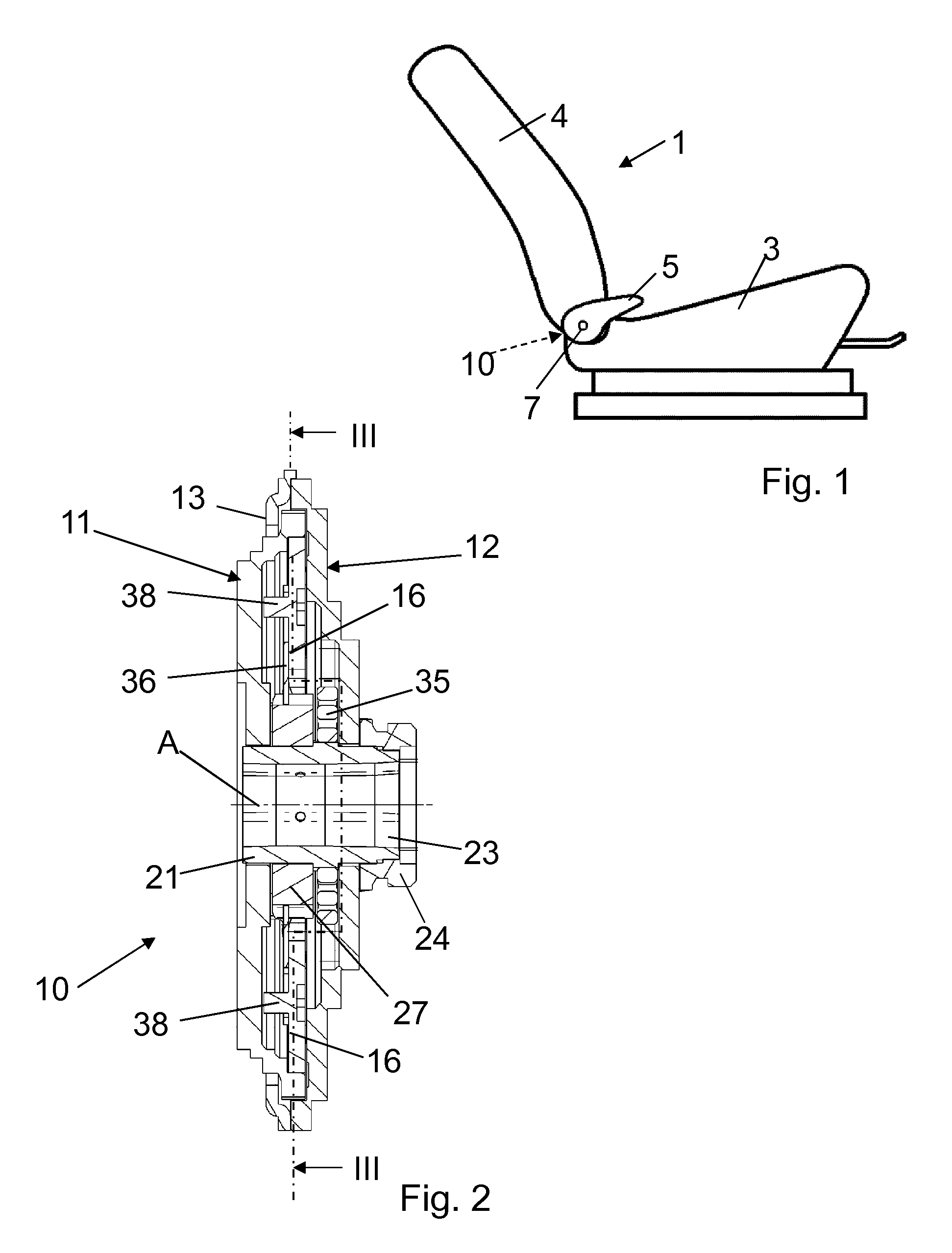
[0040]A vehicle seat 1 for a motor vehicle has a seat part 3 and a backrest 4 which is able to be adjusted in its inclination relative to the seat part 3. For adjusting the inclination of the backrest 4, a transmission rod 7 is rotated manually, for example by means of a first hand lever 5, said transmission rod being arranged horizontally in the transition region between the seat part 3 and the backrest 4. On both sides of the vehicle seat 1 the transmission rod 7 engages in a fitting 10. The transmission rod 7 defines the directional information of a cylinder coordinate system used.

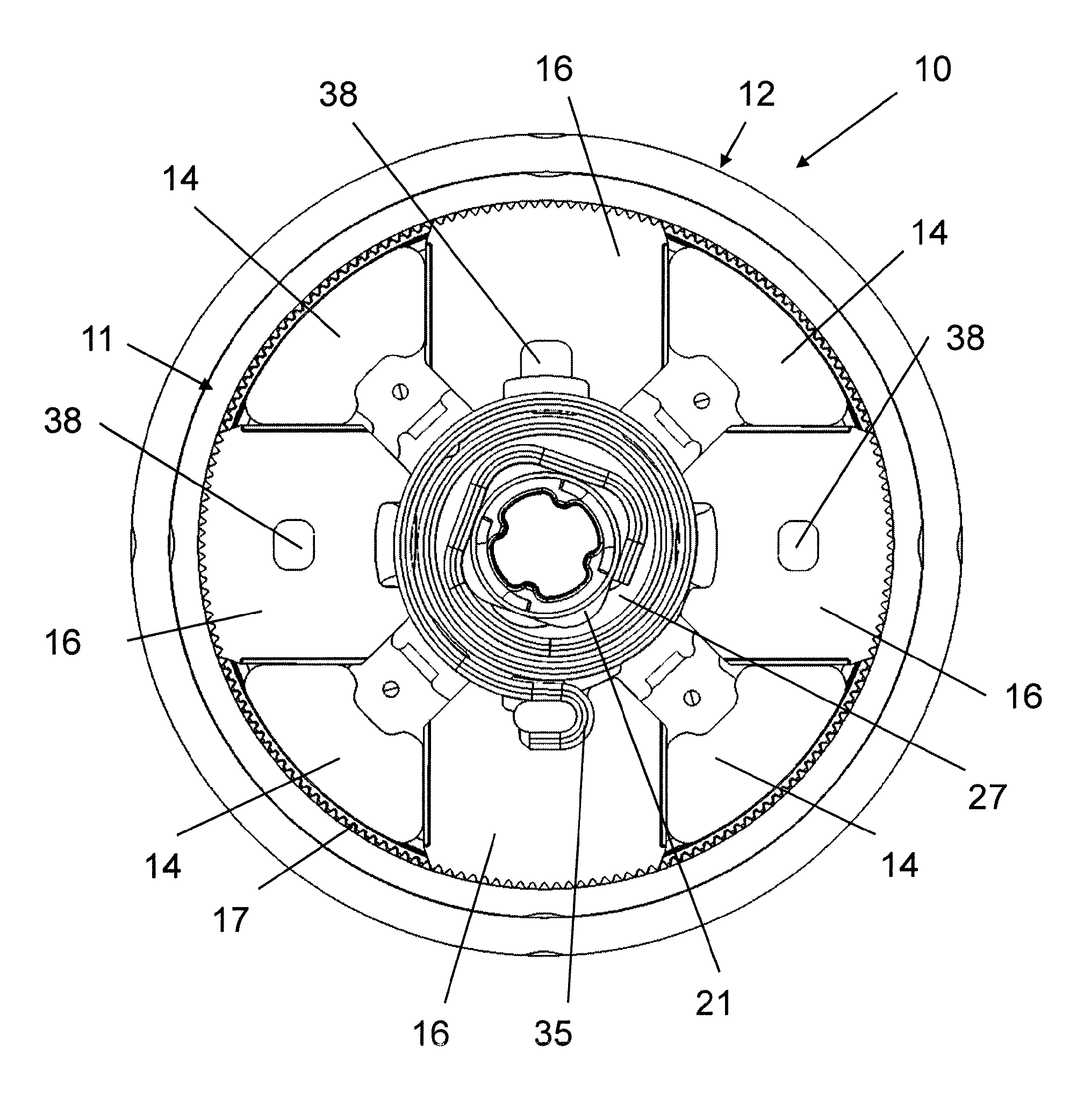
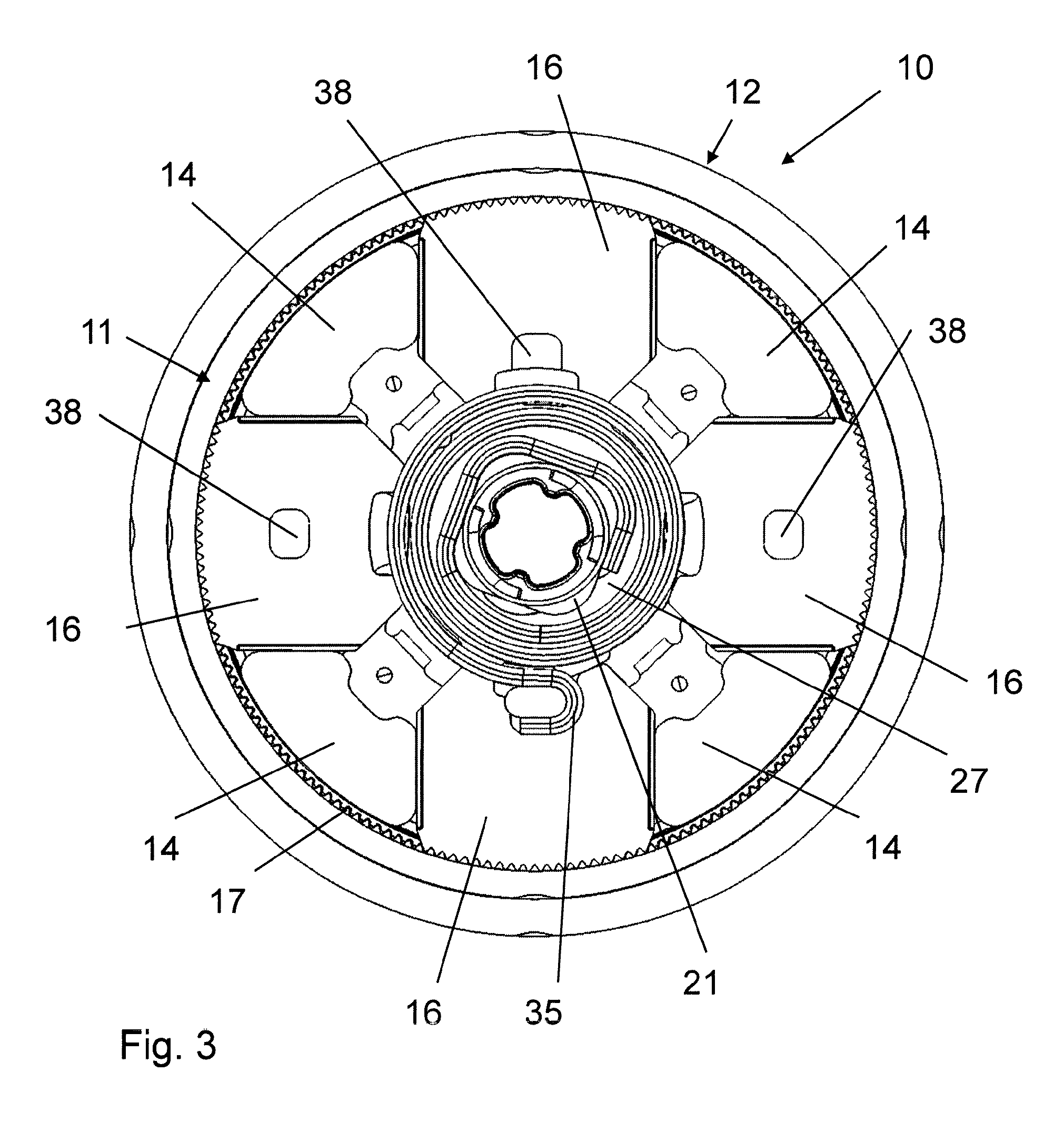
[0041]The fitting 10 has a first fitting part 11 and a second fitting part 12 which are able to be rotated relative to one another about an axis A. The axis A in the present case is aligned with the central axis of the transmission rod 7. The two fitting parts 11 and 12 may in each case approximately describe a circular disk shape. Both fitting parts 11 and 12 preferably consist of metal, in particular ...


PUM


Abstract

A vehicle seat fitting has a fitting parts (11, 12) have a sprocket (17) and guide segments (14), a bar (16) guided by the guide segments between a locked and unlocked state that interact with the sprocket. The bar has bar cams (16a, 16b). An eccentric (27) is rotatably mounted around a rotation axis (A) and in a transition from unlocked to the locked, engages the bar with a force for clamping the bar against the sprocket. The eccentric has eccentric cams (28, 128) interacting with the bar cams. The first eccentric cam has a cam section (28.2) which runs in the peripheral direction concentrically around the axis. The cam section is arranged upstream in the closing direction of a further cam section (28.4) that has a cam contour running radially outwards downstream in the closing direction relative to the concentrically peripheral contour for clamping the bar against the sprocket.

Description

CROSS REFERENCE TO RELATED APPLICATIONS[0001]This application is a United States National Phase Application of International Application PCT / EP2013 / 070151 filed Sep. 27, 2013 and claims the benefit of priority under 35 U.S.C. §119 of German Patent Applications DE 10 2012 019 698.9 filed Oct. 4, 2012 and DE 10 2012 023 057.5 filed Nov. 22, 2012, the entire contents of which are incorporated herein by reference.FIELD OF THE INVENTION[0002]The invention relates to a fitting for a vehicle seat, in particular for a motor vehicle seat, having a first fitting part and a second fitting part which are able to be rotated relative to one another about an axis, wherein a toothed ring is formed on the first fitting part and guide segments are formed on the second fitting part, at least one locking bar which is radially displaceably guided by means of the guide segments between a locked state and an unlocked state, and which in the locked state cooperates with the toothed ring in order to lock th...

Claims


Application Information

Patent Timeline
Patent Type & Authority Patents(United States)
IPC IPC(8): B60N2/235B60N2/20B60N2/44B60N2/90
CPCB60N2/2356B60N2/20B60N2/235B60N2/4435B60N2/22B60N2/236
Inventor PETERS, CHRISTOPHLEHMANN, ULRICH
Owner KEIPER SEATING MECHANISMS CO LTD
Learn More