Resonance-type non-contact power supply system

a power supply system and non-contact technology, applied in the direction of charging stations, electric vehicle charging technology, transportation and packaging, etc., can solve the problems of transmission loss, transmission efficiency drop, and inability to reduce the variation of characteristic impedance, so as to reduce unnecessary radiated electromagnetic fields and prevent transmission efficiency drop

Active Publication Date: 2016-11-01
YAZAKI CORP
View PDF33 Cites 0 Cited by
  • Summary
  • Abstract
  • Description
  • Claims
  • Application Information

AI Technical Summary

Benefits of technology

[0018]According to the exemplary embodiment, a technique to prevent the transmission efficiency from dropping and reduce the unnecessary radiated electromagnetic fields in the resonance-type non-contact power supply system can be provided.

Problems solved by technology

However, additional components become necessary when the non-contact power supply system is mounted in an electronic device or an automobile power supply system.
According to the technique using Litz wires disclosed in JP-A-2010-40699 and JP-A-5-344602, there is a problem that the variation of the characteristic impedance cannot be reduced although the transmission loss can be reduced.
(1) When a coaxial cable is used for the transmission path, an electric current flows through not only the inner side but also the outer side of a coaxial cable outer conductor 64 of the primary coaxial cable (the power-transmission-side coaxial cable 60), and a radiated electromagnetic field occurs.
(2) Because part of the electromagnetic field from a primary coil 30 is coupled with the coaxial cable outer conductor 64 and an induced current flows, a radiated electromagnetic field occurs.
(3) Because all of the electromagnetic field from a secondary resonance coil 45 is not necessarily coupled with a secondary coil 40, part of the electromagnetic field is coupled with a coaxial cable outer conductor 74 of a power-receiving-side coaxial cable 70, and an induced current flows, a radiated electromagnetic field occurs.
However, the induced current that is the cause of the transmission loss cannot be prevented from occurring by this technique.
Further, there are the following problems: power supply operations are disturbed, the weight of the overall system increases, and the system is difficult to be mounted.

Method used


Image

  • Resonance-type non-contact power supply system
  • Resonance-type non-contact power supply system
  • Resonance-type non-contact power supply system

Examples


Embodiment Construction

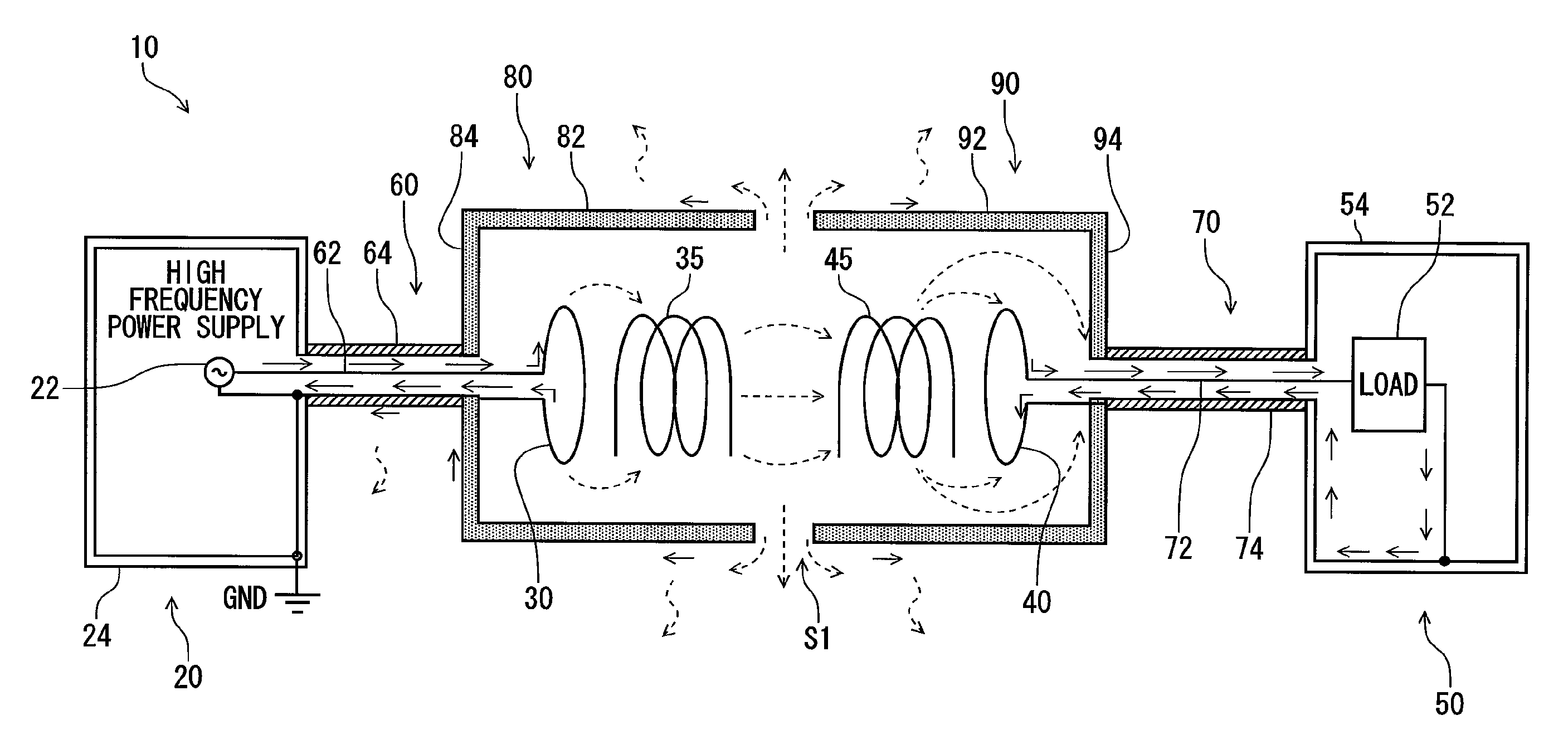
[0032]Below, modes for carrying out the invention (hereinafter referred to as “embodiments”) are explained with reference to the figures. An outline of the present embodiment is as follows. In the resonance-type non-contact power supply system of the present embodiment, areas around a primary and a secondary resonance coil parts are covered with metal cases (metal shields), and the metal cases are electrically connected with the outer conductors of coaxial line cables. With the above construction, the transmission efficiency can be improved and the radiated electromagnetic field can be reduced in a simple and low cost way. By placing the metal cases only around the resonance coil parts, the weight can be less than that when the whole system is shielded. Thereby, even if the system is carried on a mobile body such as a vehicle, the increase of the energy consumption due to the weight increase can be inhibited. The details are described as follows.

[0033]FIG. 5 is a figure which schema...


PUM

PropertyMeasurementUnit
frequencyaaaaaaaaaa
diameteraaaaaaaaaa
diameteraaaaaaaaaa

Abstract

A resonance-type non-contact power supply system includes a power-transmission-side metal shield to cover an area around a primary coil and a primary resonance coil. A coaxial cable outer conductor of a power-transmission-side coaxial cable and the power-transmission-side metal shield are threadedly engaged using a coaxial male connector and a coaxial female connector.

Description

CROSS REFERENCE TO RELATED APPLICATIONS[0001]This application is a continuation of PCT application No. PCT / JP2012 / 060796, which was filed on Apr. 20, 2012 based on Japanese Patent Application (No. 2011-096355) filed on Apr. 22, 2011, the contents of which are incorporated herein by reference. Also, all the references cited herein are incorporated as a whole.TECHNICAL FIELD[0002]The present invention relates to a resonance-type non-contact power supply system.BACKGROUND ART[0003]A technique in which electric power is supplied to a load device by a non-contact system is known. As a product into which the technique is applied, a mobile phone charging system has become popular in general. Furthermore, in recent years, the non-contact power supply system is practically used even as a power supply system for electric vehicles, and various standards are established in view of practical operations.[0004]There are various types of non-contact power supply system. A power supply system for el...

Claims


Application Information

Patent Timeline
Patent Type & Authority Patents(United States)
IPC IPC(8): B60L5/00H04B5/00H02J7/02H02J5/00H01F38/14H01F27/36H01F27/02B60L11/18
CPCH01F38/14B60L5/005B60L11/182H01F27/02H01F27/362H02J5/005H02J7/025H02J50/12H04B5/0037Y02T10/7005Y02T10/7072Y02T90/122Y02T90/14B60L2210/10B60L2210/30B60L2210/40B60L2270/147Y02T90/12B60L53/30B60L53/122Y02T10/72Y02T10/70H01F27/363H01F27/366H02J50/70B60L53/12H01F27/36
Inventor NAKAHARA, TAKAHIROYANAGIDA, YOUNGAHU, ANTONY
Owner YAZAKI CORP
Why Eureka
Try Eureka