Identifying method and device for detecting specific region of translucent medium

a technology of translucent medium and identification method, which is applied in the direction of measurement devices, instruments, computing, etc., can solve the problems of increasing the manufacturing cost of translucent medium, increasing the acquisition cost of sensing machines, and not easy for sensing machines, so as to save equipment acquisition costs and reduce complexity in circuit configuration.

Active Publication Date: 2016-11-08
HI TOUCH IMAGING TECH CO LTD
View PDF6 Cites 0 Cited by
  • Summary
  • Abstract
  • Description
  • Claims
  • Application Information

AI Technical Summary

Benefits of technology

[0030]Therefore, as compared with the prior art, the present disclosure identifying method and device only needs to make a self comparison between the light-intensity signal sensed at one time instant and the divide and stabilize light-intensity signal sensed at the one time instant without cooperating with the additional signal amplifier and digital / analog conversion circuit. Not only is the equipment acquisition cost saved, but the complexity in circuit configuration is also reduced.

Problems solved by technology

Due to the light transmission character of a translucent medium, such as a translucent card or a translucent slide, it is not easy for a sensing machine to distinguish whether the translucent medium has passed, and even more, the sensing machine cannot detect a relative position of the translucent medium.
Not only is the acquisition cost of sensing machine increased, but the manufacturing cost of the translucent medium is also increased.

Method used


Image

  • Identifying method and device for detecting specific region of translucent medium
  • Identifying method and device for detecting specific region of translucent medium
  • Identifying method and device for detecting specific region of translucent medium

Examples


first embodiment

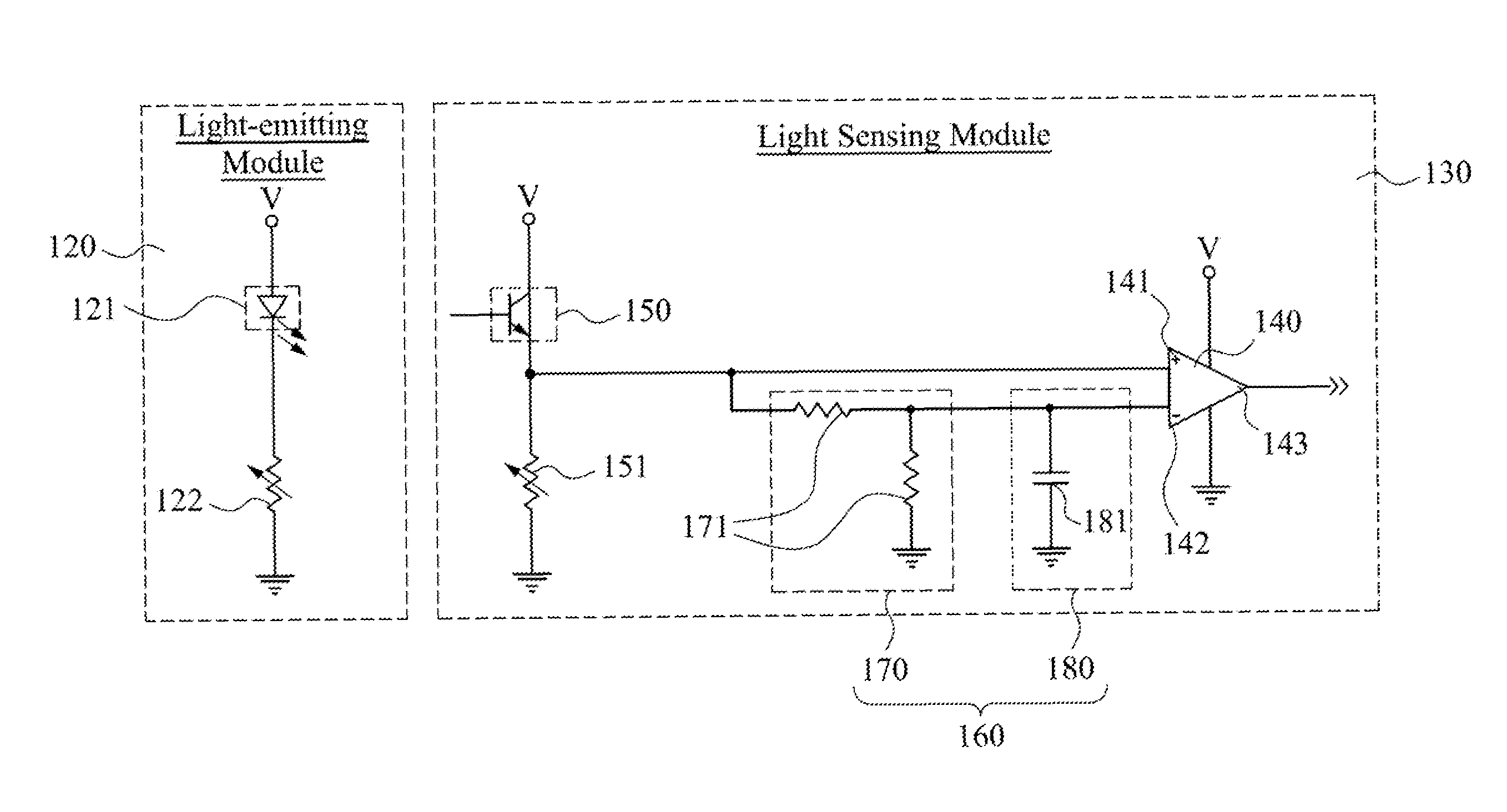
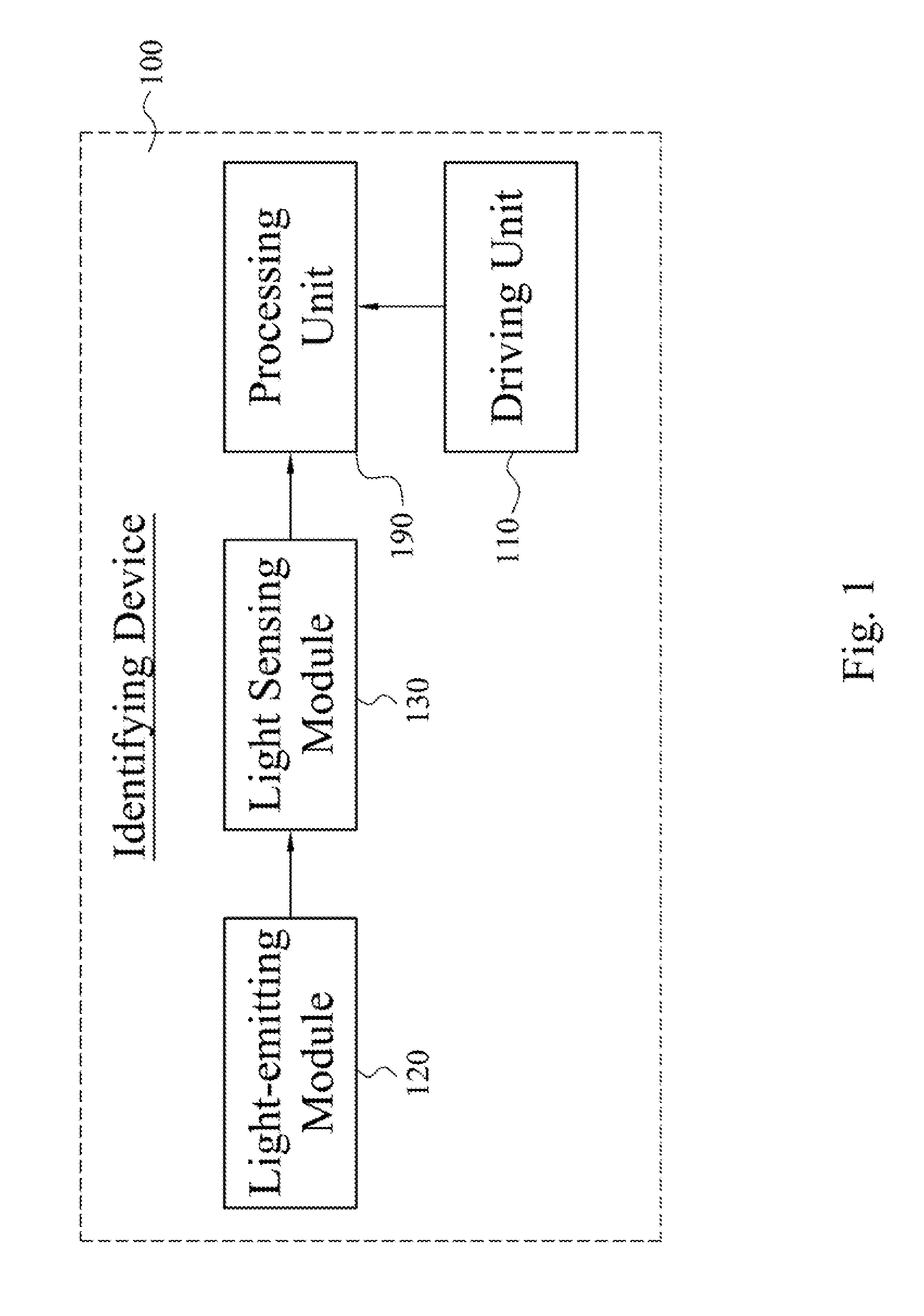
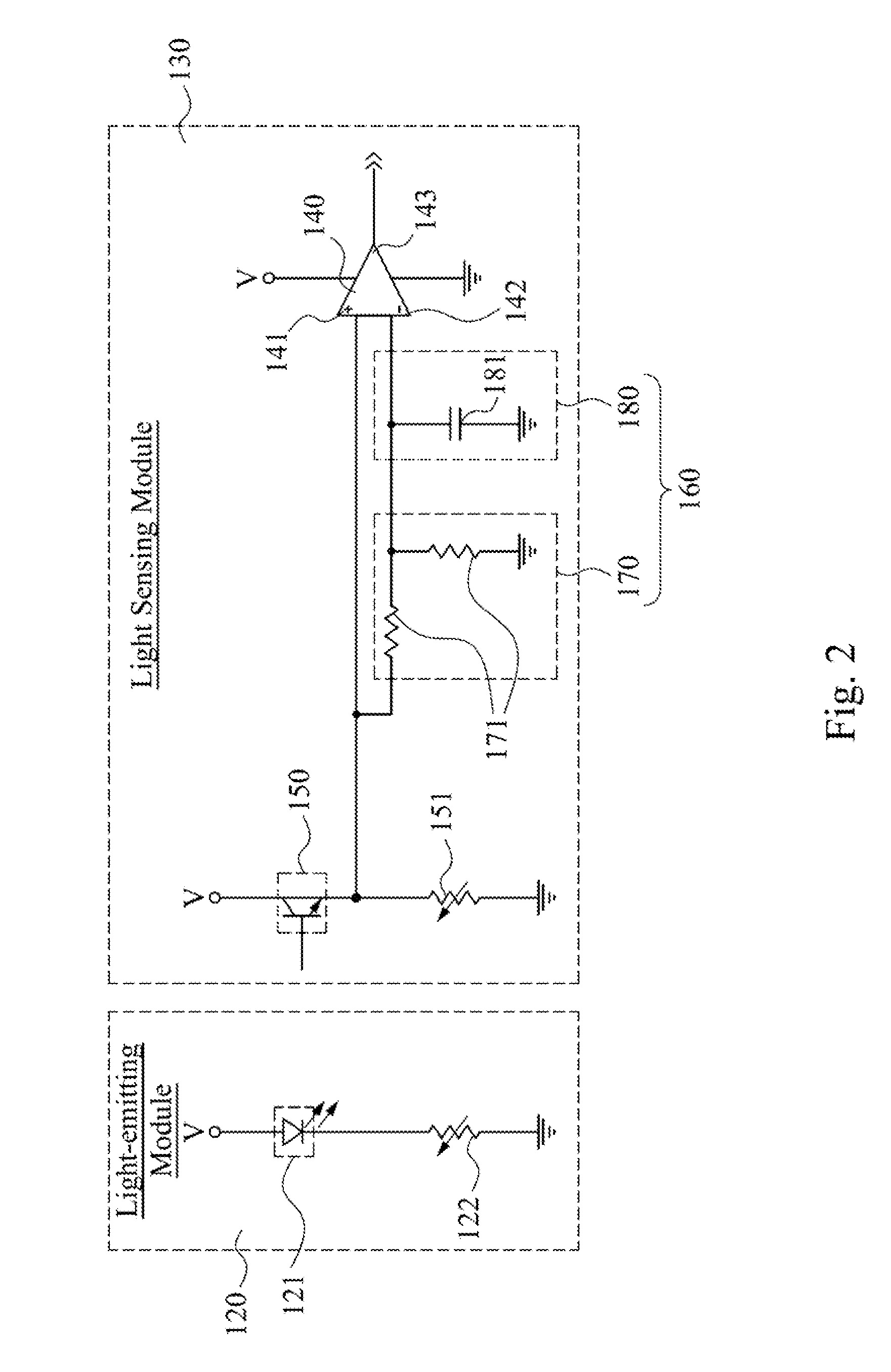
[0045]FIG. 1 depicts a block diagram of an identifying device 100 for detecting a specific region of a translucent medium according to a first embodiment of this disclosure. As shown in FIG. 1, an identifying device 100 for detecting a specific region of a translucent medium according to the present disclosure comprises a driving unit 110, a light-emitting module 120, a light sensing module 130, and a processing unit 190. The driving unit 110 is configured to drive a translucent medium to move linearly along a direction. The light-emitting module 120 is configured to emit light intersecting the direction. The light sensing module 130 is configured to receive the light emitted by the light-emitting module 120 and generate a first light-intensity signal corresponding to an intensity of the light. Whenever the light sensing module 130 receives and senses the first light-intensity signal at one time instant, the voltages of the first light-intensity signal is divided and stabilized by t...

second embodiment

[0052]According to the present embodiment, the present disclosure identifying device 100 for detecting the specific region of the translucent medium and the present disclosure identifying method for detecting the specific region of the translucent medium are utilized to detect an edge of a translucent medium so as to serve as a basis for positioning. For example, when the translucent medium is a translucent card (or transparent card) and the translucent card has been detected, a subsequent action for printing the card or reading data from the card can be performed. For example, an automated teller machine identifies that the translucent card has passed a specified region so as to initiate relevant functions for reading the card.

[0053]FIG. 4A to FIG. 4C depict schematic diagrams of operations when the light-emitting module 120, the light sensing module 130, and a translucent medium 200 are at different relative positions and signal changes correspondingly according to a second embodi...

third embodiment

[0062]According to the present embodiment, a present disclosure identifying device and identifying method for detecting a specific region of a translucent medium are utilized for detecting a translucent grating structure, especially for detecting positions of various gratings in the grating structure so as to serve as a basis for positioning for subsequent printing.

[0063]FIG. 5A to FIG. 5C depict schematic diagrams of operations when the light-emitting module 120, the light sensing module 130, and a translucent grating structure 210 are at different relative positions and signal changes correspondingly according to a third embodiment or this disclosure. Owing to the light transmission character of a translucent grating structure 210, the light L emitted from the light-emitting diode 121 can pass through the translucent grating structure 210 and be sensed by the light detection transistor 150. For example, as shown in FIG. 5A, the translucent grating structure 210 is composed of tran...


PUM


Abstract

An identifying method for detecting a specific region of a translucent medium provided includes steps as follows. A light sensing module is adjusted to allow an operation point of the light sensing module to be in an active region. Light is emitted to a driven translucent medium by a light-emitting module. The light been passed through the translucent medium is sensed by the light sensing module to generate a first light-intensity signal based on the light sensed at one time instant, and the voltages of the first light-intensity signal are regulated to derive a second light-intensity signal. A voltage level of the first light-intensity signal is compared with that of the second light-intensity signal to generate a comparison result. A determination of whether a specific region of the translucent medium is positioned between light sensing module and light-emitting module is made based on the comparison result.

Description

RELATED APPLICATIONS[0001]This application claims priority to Taiwan Application Serial Number 104103762, filed Feb. 4, 2015, which is herein incorporated by reference.BACKGROUND[0002]1. Field of Disclosure[0003]The present disclosure relates to an identifying method and device for detecting a specific region of a translucent medium. More particularly, the present disclosure relates to an identifying method and device for detecting a specific region of a translucent medium based on a self comparison result of a light sensing intensity sensed at one time instant.[0004]2. Description of Related Art[0005]Due to the light transmission character of a translucent medium, such as a translucent card or a translucent slide, it is not easy for a sensing machine to distinguish whether the translucent medium has passed, and even more, the sensing machine cannot detect a relative position of the translucent medium. In order to allow the sensing machine to be able to detect the translucent medium...

Claims


Application Information

Patent Timeline
Patent Type & Authority Patents(United States)
IPC IPC(8): G01J1/44G01B11/14
CPCG01J1/44G01B11/14G06K13/063G06K13/067
Inventor CHEN, TSUNG-YUEH
Owner HI TOUCH IMAGING TECH CO LTD
Why Eureka
Try Eureka