Transmission switching mechanism device

A technology of conversion mechanism and trowel, which is applied in the direction of grinding drive device, grinding/polishing safety device, grinding machine parts, etc. Great improvement, uneven floor surface uniformity and other problems, to achieve high-quality and efficient grinding and polishing operations, saving equipment purchase costs, and simple structure

Pending Publication Date: 2018-08-24
上海抛丸机械设备制造有限公司
View PDF0 Cites 8 Cited by
  • Summary
  • Abstract
  • Description
  • Claims
  • Application Information

AI Technical Summary

Problems solved by technology

However, there is a big defect in this technology. Because the structure determines that the grinding disc of this scheme has only one rotation around the main shaft of the trowel, the uniformity of the ground surface is not completely consistent, and it is still not perfect. Meets high standards for polished concrete floors
In response to this deficiency, another solution has been improved, that is, each grinding disc on the connecting disc can be rotated freely. Therefore, during operation, in addition to one of the grinding discs revolving with the connecting disc, due to the reaction force of the ground grinding contact, the grinding disc Make a self-rotation in the opposite direction, but this kind of self-rotation is a passive rotation. When there is a defect in the flatness of the ground, the speed of each grinding disc is not consistent. Efficiency has not improved much

Method used


Image

  • Transmission switching mechanism device
  • Transmission switching mechanism device
  • Transmission switching mechanism device

Examples


Embodiment 1

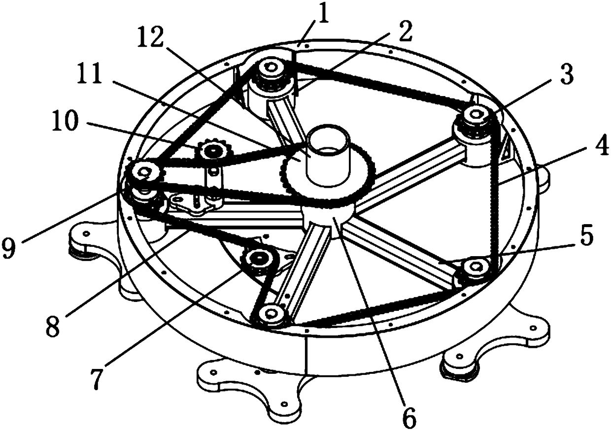
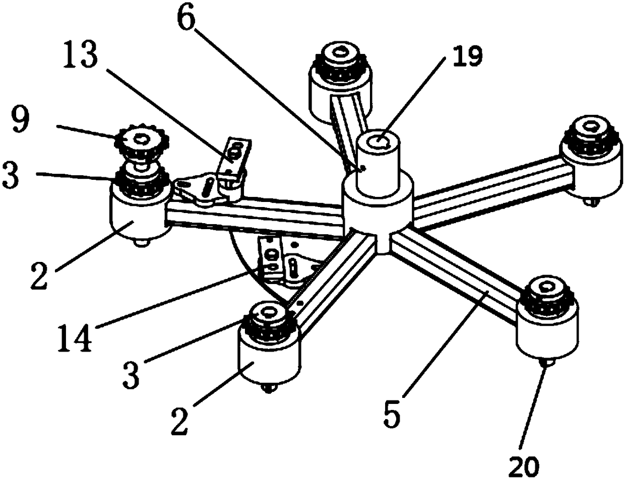
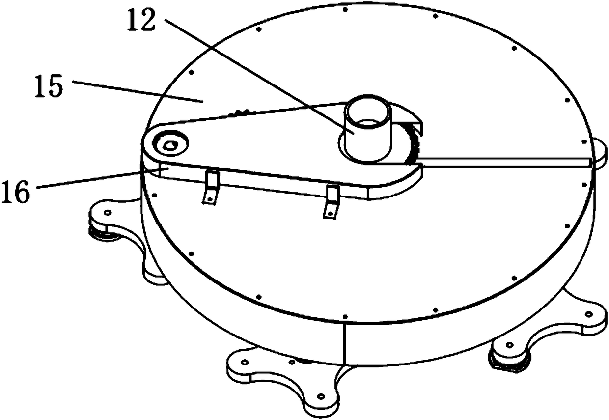
[0033] Such as Figure 1-4 As shown, a transmission conversion mechanism device is installed on the driving main shaft of the troweling machine. The device includes an intermediate connecting piece 6 linked with the main shaft of the troweling machine, and several rotating discs 17. The whole device Together with the main shaft of the troweling machine, it rotates synchronously. When each rotating disk 17 rotates on its own, it revolves together with the whole device to perform grinding and polishing operations.

[0034] The specific structure is as follows: the device includes base 1, bearing seat 2, sprocket a3, long chain 4, connecting rod 5, intermediate connecting piece 6, tensioning sprocket a7, chain 8, sprocket b9, tensioning sprocket b10, large sprocket 11, cylindrical sleeve 12, tensioning sprocket installation frame a13, tensioning sprocket installation frame b14, upper cover plate 15, sprocket cover 16, rotating disc 17 and grinding disc 18, the bearing seat 2 The...

Embodiment 2

[0046] The connecting rod 5 is a round steel, and its main function is to ensure the design positioning and rigidity of the device.

[0047] Described sprocket a3 and sprocket b9 adopt belt pulley to replace, and described long chain 4 and chain 8 adopt belt to replace. That is to change the sprocket drive mechanism into a pulley drive mechanism to achieve the same function.

[0048] The structure of the connecting sleeve (12) can be a cylinder, or other structures. It is used as a transition connecting part to make the large sprocket (11) fixedly connected and installed with the trowel reducer, and to make the large The centerline of the sprocket coincides with the centerline of the output spindle of the trowel gearbox.

[0049] All the other are with embodiment 1.


PUM


Abstract

The invention relates to a transmission switching mechanism device installed on a trowel sheet drive main shaft of a trowel machine. The transmission switching mechanism device comprises an intermediate connection piece (6) connected with the main shaft of the trowel machine in a chained manner and a plurality of rotating disks (17), wherein the whole device and the main shaft of the trowel machine conduct synchronous rotation motion together. Each rotating disk rotates around own axis, and each rotating disk also rotates around the rotation center of the whole device together with the whole device at the same time, so that abrasive disks (18) on the rotating disks (17) are driven to conduct grinding and polishing operation. Compared with the prior art, the transmission switching mechanismdevice achieves that a driving planetary transmission mechanism is additionally arranged on an existing trowel machine or similar equipment, and then the trowel machine can efficiently conduct grinding and polishing operation at a high uniformity.

Description

technical field [0001] The invention relates to a polishing device, in particular to a transmission conversion mechanism device for a trowel (smoothing machine) or similar equipment. Background technique [0002] Polished concrete has the advantages of good decoration, good floor flatness, easy cleaning, low maintenance cost, good durability, and long life. It is very suitable for public places with high traffic. The main technological process of polished concrete construction is grinding, gap repair, curing and polishing, and the main construction equipment is a grinding and polishing machine. [0003] At present, the grinding and polishing equipment is mainly a walk-behind grinding machine, and its working width is generally not greater than 1 meter, resulting in insufficient efficiency. For large-scale projects such as large parking garages, more than a dozen or even dozens of construction grinding machines are needed The operation of the equipment requires a lot of capi...

Claims


Application Information

Patent Timeline
IPC IPC(8): B24B29/02B24B27/00B24B55/00B24B47/12B24B7/18
CPCB24B7/186B24B27/0076B24B29/02B24B47/12B24B55/00
Inventor 罗智
Owner 上海抛丸机械设备制造有限公司
Why Eureka
Try Eureka