
Power conversion device

a technology of power conversion device and power converter, which is applied in the direction of printed circuit board receptacles, electrical apparatus construction details, support structure mounting, etc., can solve the problem of undesirable long length of filter condensers, and achieve the effect of reducing the wiring distance between filter condensers and switching elements

Active Publication Date: 2016-11-08
NISSAN MOTOR CO LTD +1
View PDF60 Cites 1 Cited by
  • Summary
  • Abstract
  • Description
  • Claims
  • Application Information

AI Technical Summary

Benefits of technology

The aim of this patent is to create a power converter that reduces the distance between the filter condensers and the switching elements, making the wiring more efficient. The invention achieves this by balancing the distance between the filter condensers and switching elements, resulting in a shorter overall wiring distance.

Problems solved by technology

However, in such arrangement, the wiring for connecting IGBTs (viz., Insulated Gate Bipolar Transistor), which are switching means, to the filter condensers has a long length undesirably.

Method used


Image

  • Power conversion device
  • Power conversion device
  • Power conversion device

Examples


Embodiment Construction

[0021][Outline of Power Conversion System 1]

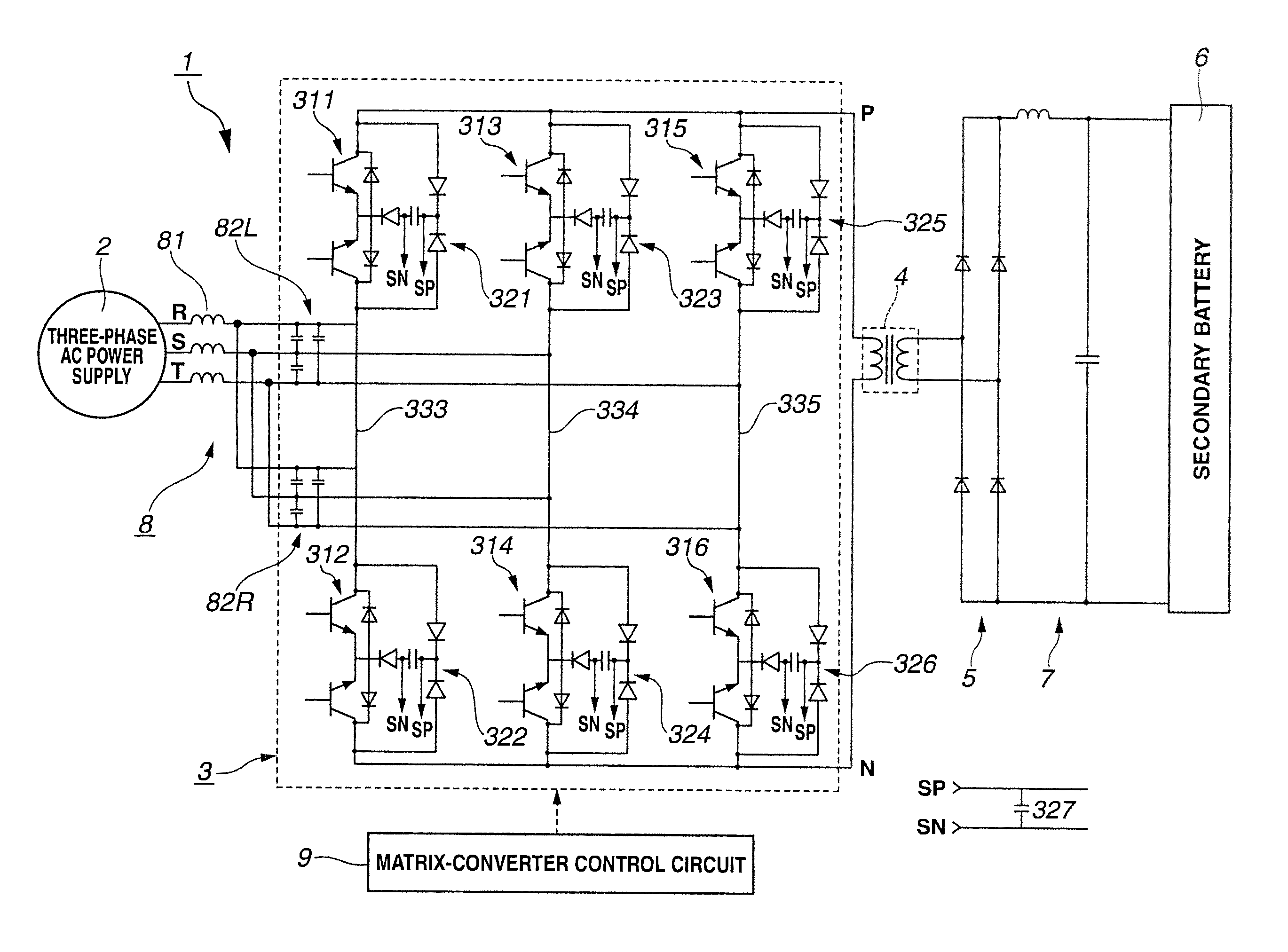
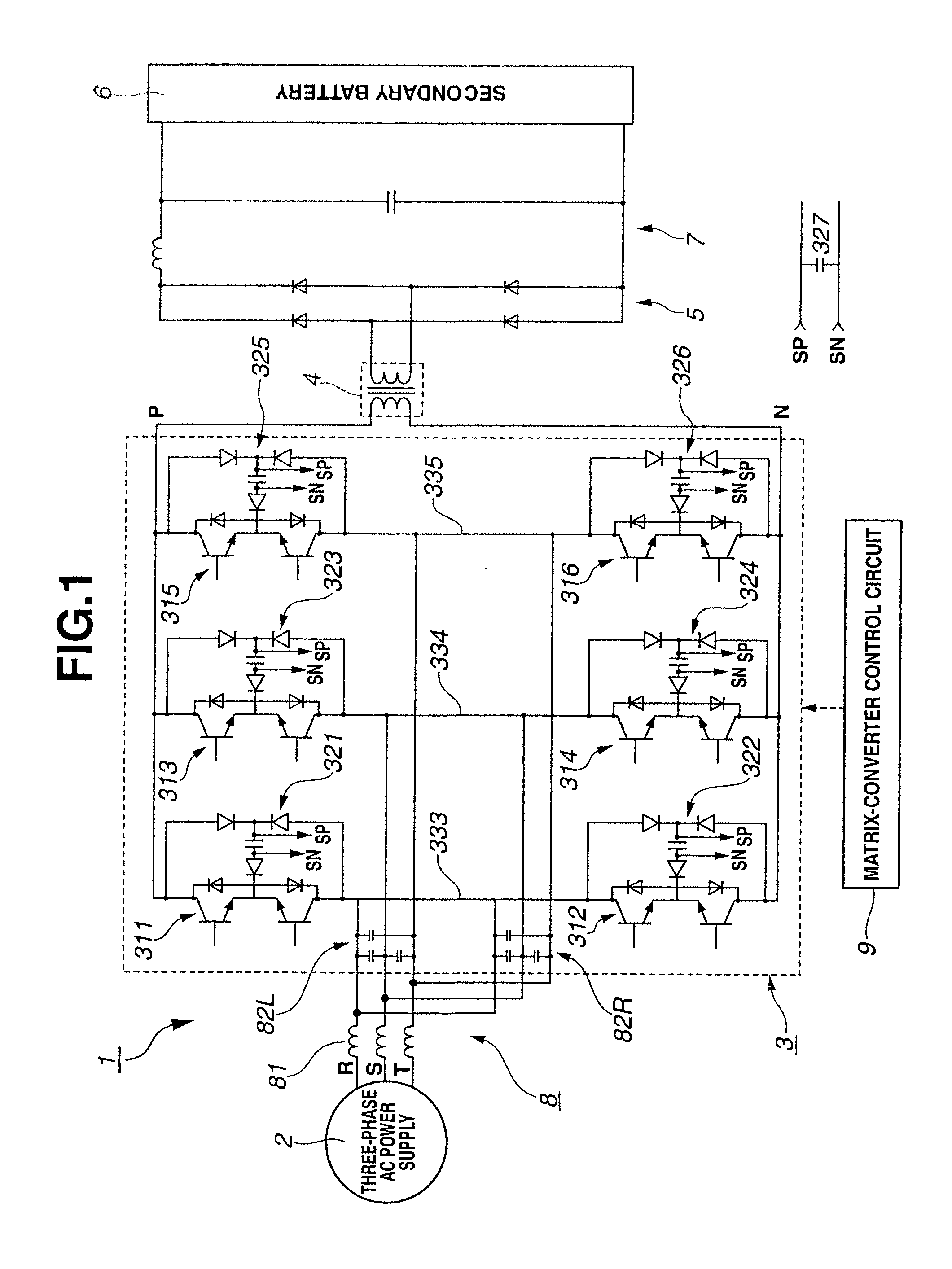
[0022]First, a brief outline of a power conversion system to which an embodiment of the present invention is practically applied will be described with reference to FIG. 1. The power conversion system 1 of this example is a system in which a three-phase AC power supplied from a three-phase AC power supply 2 is directly converted to a single-phase AC power by a power converter 3 of the embodiment of the present invention, and after the voltage of the converted AC power is stepped up or down by a transformer 4 to a suitable value, the transformed AC power is converted by a rectifier 5 to a DC power to charge a secondary battery 6. It is to be noted that denoted by numeral 7 is a smoothing circuit.

[0023]In power conversion system 1 of this example, output lines (indicated by R-phase, S-phase and T-phase) to which the three-phase AC power is supplied from three-phase AC power supply 2 have at each phase a filter circuit 8 that dampens a higher...


PUM


Abstract

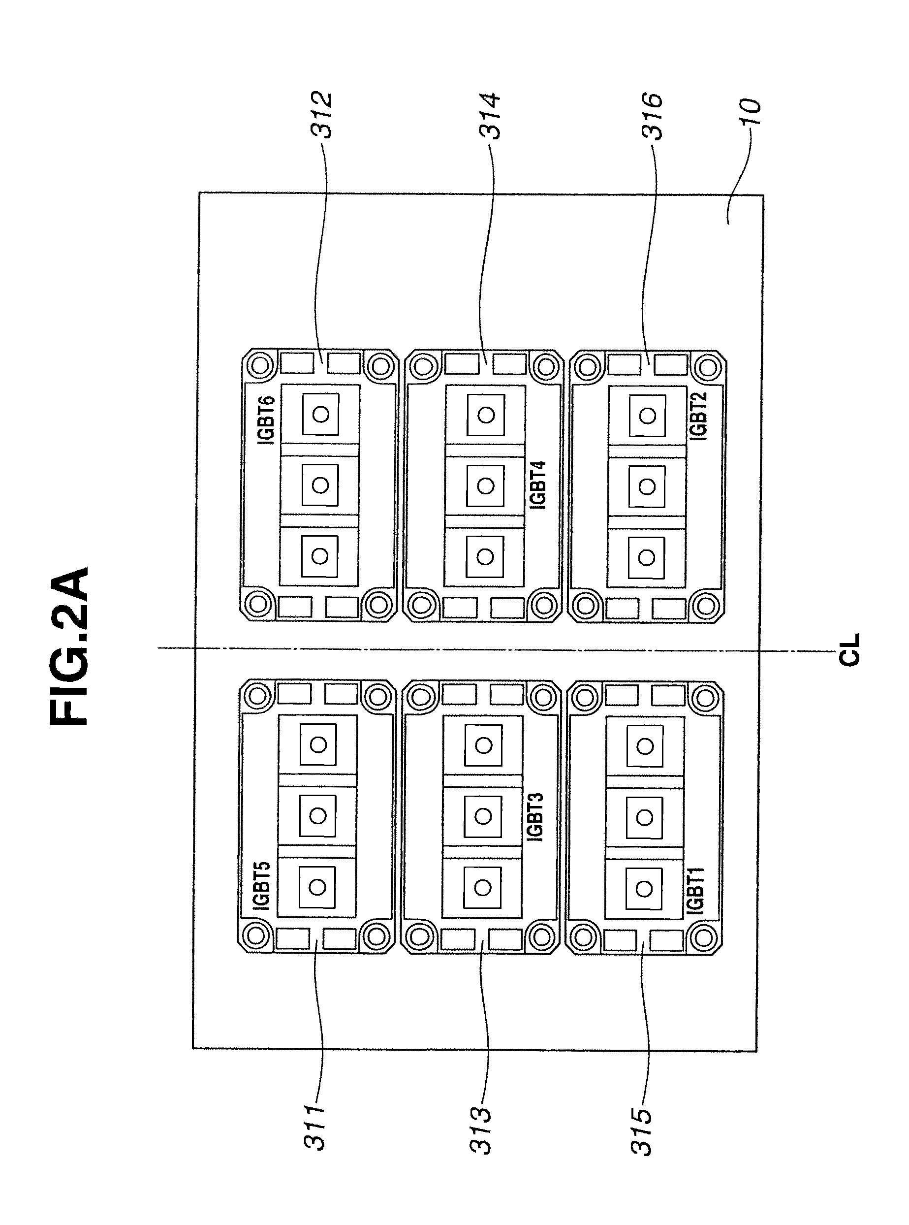
Provided is a power converter 3 that directly converts polyphase AC power to AC power. A converter circuit has a plurality of first switching elements 311, 313 and 315 and a plurality of second switching elements 312, 314 and 316, both of which are connected to each phase R, S or T of the polyphase AC power to enable switching for turning on current-carrying bidirectionally. Condensers 821 to 826 are provided between phases. Input terminals of the first switching elements and those of the second switching elements are arranged to form respective lines. Some of the plurality of condensers 821 and 822 are arranged to be angled relative to the arrangement direction of the terminals. The wiring distance between the condensers and the switching elements can be shortened.

Description

TECHNICAL FIELD[0001]The present invention relates to a power conversion device or a power converter that directly converts AC power of commercial frequency to an arbitrary PC power.BACKGROUND ART[0002]As a power converter that has the small number of components to enable downsizing of the device and directly and effectively converts AC power to AC power, a matrix-converter has been known (Patent Document 1).[0003]In the above-mentioned conventional matrix-converter, filter condensers constituting a filter circuit are arranged on a substrate forming a line in a longitudinal direction and installed in a unit case. However, in such arrangement, the wiring for connecting IGBTs (viz., Insulated Gate Bipolar Transistor), which are switching means, to the filter condensers has a long length undesirably.PRIOR ART DOCUMENTPatent Document[0004]Patent Document 1: Japanese Laid-open Patent Application (Tokkai) 2006-333590SUMMARY OF INVENTION[0005]An object of the present invention is to provid...

Claims


Application Information

Patent Timeline
Patent Type & Authority Patents(United States)
IPC IPC(8): H02M5/14H02M5/293H02M5/00H05K7/14H02M7/00H02M1/42
CPCH02M5/00H02M5/293H02M7/003H05K7/1432H02M1/4258Y02B70/126Y02B70/10H05K7/14329
Inventor KOYANO, HIRONORINAKAMURA, TAKAMASASAITO, MASAOYAMAMOTO, KOUJIMATSUKAWA, TSUTOMUKOSHIJO, MANABUITOH, JUNICHIOHNUMA, YOSHIYA
Owner NISSAN MOTOR CO LTD
Learn More