
Junctional tourniquet

a tourniquet and junction technology, applied in the field of tourniquets, can solve the problems of difficult application to a fallen patient, inability to prevent the loosening of the pressure points, and the device is not suitable for the wound in the trunk/thigh junction

Active Publication Date: 2016-11-15
BOARD OF RGT UN1VERSITY OF TEXAS SYST +1
View PDF1 Cites 2 Cited by
  • Summary
  • Abstract
  • Description
  • Claims
  • Application Information

AI Technical Summary

Benefits of technology

Enables easy application and secure, adjustable pressure at multiple wound sites, reducing the risk of pressure points loosening and improving effectiveness in preventing hemorrhage at the junctional region, particularly suitable for diverse body types and injury locations.

Problems solved by technology

However, this device is ill suited for wounds in the trunk / thigh junction as it does not have the ability to apply pressure to the junctional area.
However, this design is difficult to apply to a fallen patient, can only apply pressure to a single wound location, has several removable parts that can be lost in shipping, storage or use, includes straps that are prone to slipping out of place, does not have the ability to prevent the pressure points from loosening and does not allow pressure points to be modifiably positioning for differing body types and wound locations.
With body armor, there is a “weakness” where the body armor does not cover the junctional region and, therefore, wounds in this area have become more common.
In fact, some studies report that with devices such as the C-A-T and the increased use of body armor, junctional wounds are now more likely to cause preventable combat death than wounds localized to limbs (including the complete loss of a limb).

Method used


Image

  • Junctional tourniquet
  • Junctional tourniquet
  • Junctional tourniquet

Examples


Embodiment Construction

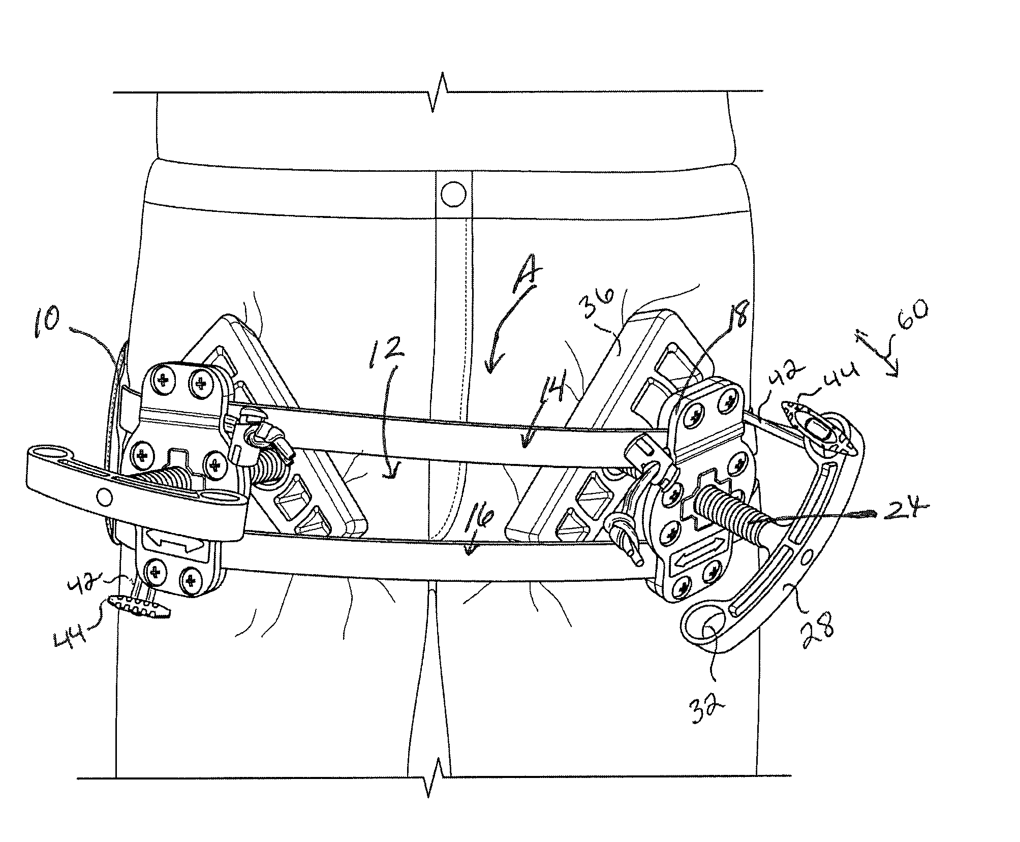
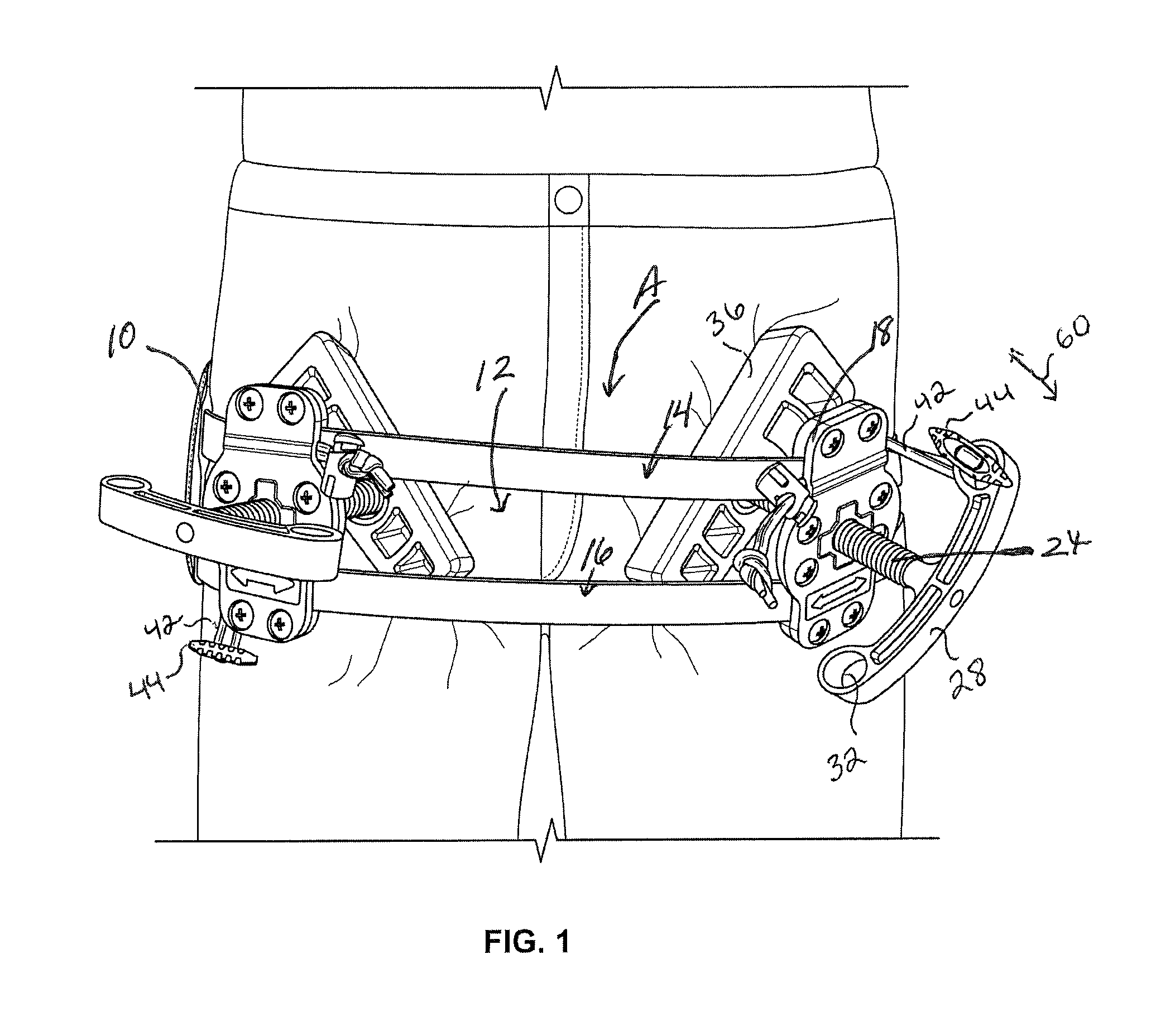
[0021]Referring to FIG. 1, the junctional tourniquet A is shown having a strap 10 encircling an individual. The strap include an opening 12 having an upper portion 14 and lower portion 16. The opening allows the base plates to be slidably attached to eh strap while also allowing the shaft to extend through the strap.

[0022]A first base plate 18 can include a top member 20 (FIG. 4) and a bottom member 22 that sandwiches the top and bottom portion of the strap allowing the base place to slide along the top and bottom portion of the strap to position the base plate above the location on the individual where compression is desired. The ability to position the base plates along the strap allows the compressive force to be placed in the proper location based upon the body type and injury and injury location of the individual. In one embodiment, the top member and the bottom member of the base plate are secured through a plurality of screws.

[0023]A shaft 24 is received in a base plate openi...


PUM


Abstract

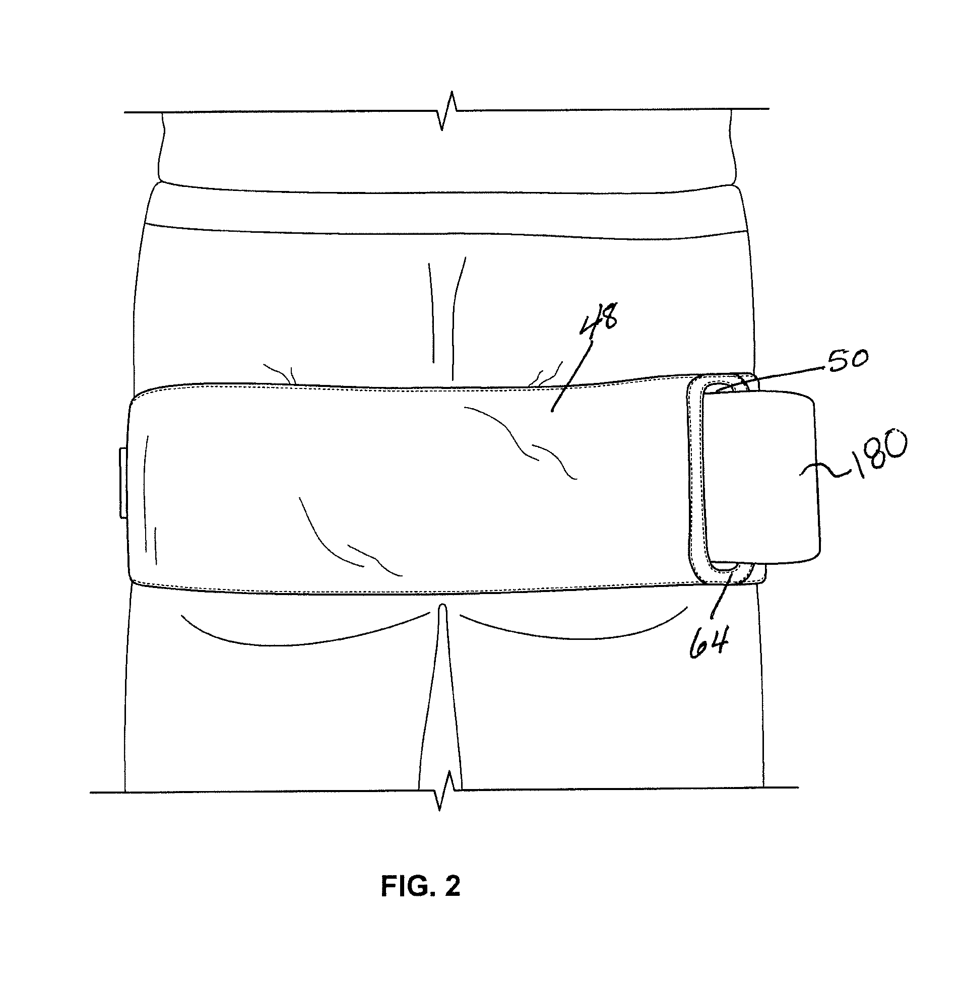
The present invention is a tourniquet comprising: a strap; a pelvic pad included in the strap having a pocket defined in the pelvic pad for receiving a semi-rigid stiffening member; base plates slidably attached to the strap allowing the base plates to be positioned along the strap; a threaded shaft received in each of the base plates; a pressure pad removable attached to a distal end of each of the shafts; a handle attached to a proximal end of each of the shafts having openings defined in each end of the handle; and, a rotational arresting strap attached to each base plate having a securing tab that can be received in one of the handle openings thereby preventing the shaft from rotating when the securing tab is received in sand handle opening.

Description

CLAIM OF PRIORITY[0001]This patent application claims priority on U.S. Patent Provisional Application Ser. No. 61 / 625,729 filed Apr. 18, 2012.FIELD OF THE INVENTION[0002]This invention is directed to a tourniquet designed to apply pressure to wounds located in the junction between the trunk and thigh and more specifically, to a tourniquet having the ability to apply pressure circumferentially with discrete pressure points in the trunk / thigh junction.BACKGROUND OF THE INVENTION[0003]Hemorrhage is one of the most common causes of preventable combat death in modern warfare. In response, efforts to create new and more effective and useful battlefield tourniquets has increased. For example, U.S. Pat. No. 4,469,099 is a Pneumatic Tourniquet described as a pneumatic tourniquet having an inflatable cuff, a pressurizing mechanism for pressurizing the cuff, a pressure relief mechanism for depressurizing the cuff, a pressure sensing mechanism for sensing the pressure to which the cuff is press...

Claims


Application Information

Patent Timeline
Patent Type & Authority Patents(United States)
IPC IPC(8): A61B17/00A61B17/132
CPCA61B17/1325A61B17/1327
Inventor SAUNDERS, DARRELFLORES-ARTOLA, RICARDOWALTERS, JOANNEDUNCAN, MICHAELMARTINEZ-LOPEZ, LESTERMARKHAM, JOSHUABRONSON, BRENTHOLCOMB, JOHN B.GATES, KEITHBURGESS, ANDY
Owner BOARD OF RGT UN1VERSITY OF TEXAS SYST
Learn More