Extrusion plate and extrusion apparatus
- Summary
- Abstract
- Description
- Claims
- Application Information
AI Technical Summary
Benefits of technology
Problems solved by technology
Method used
Image

Examples
first embodiment
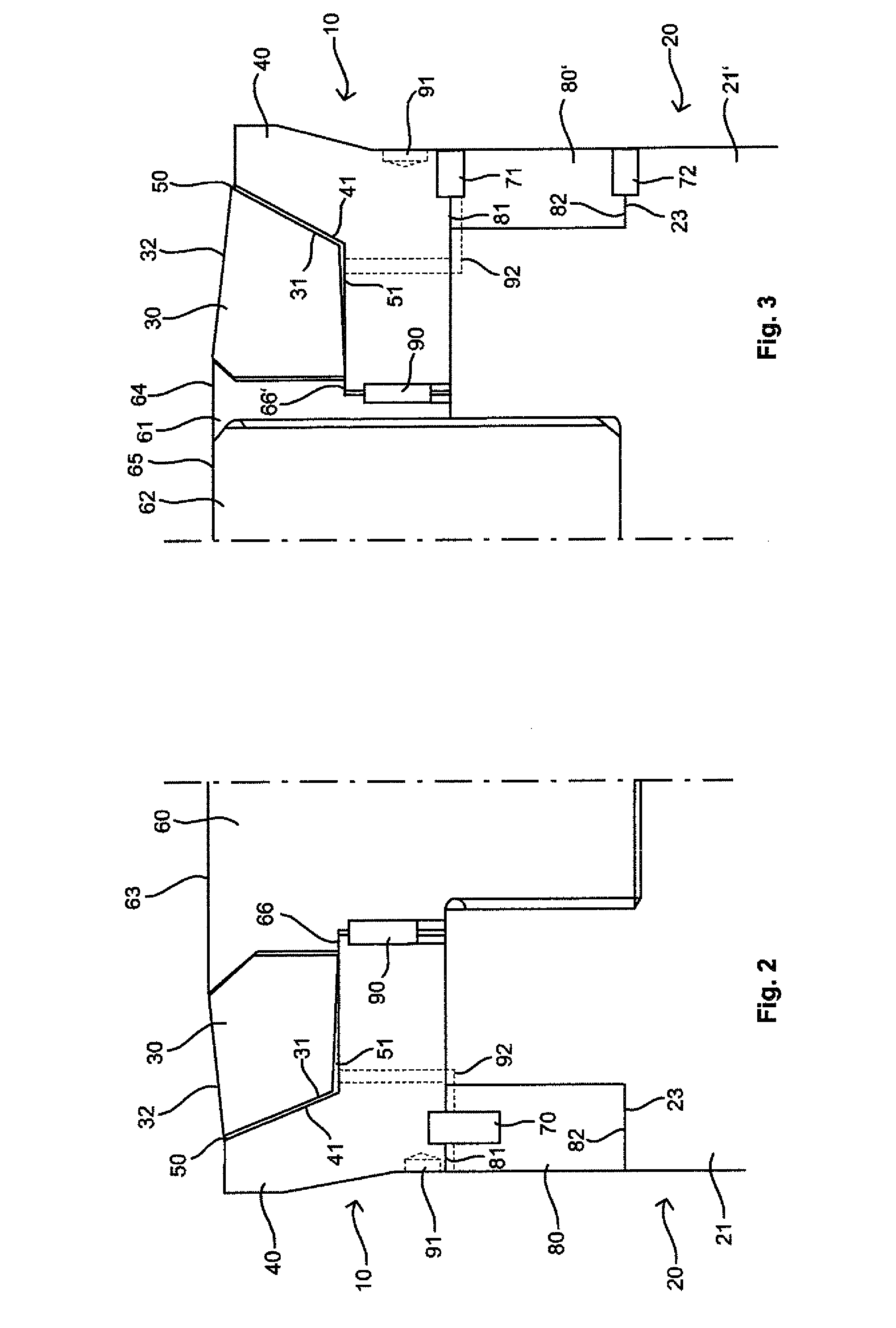
[0052]FIG. 2 shows a dummy block according to the invention, in a schematic half-section, in which the connecting element is configured as a connecting stud 60 that is screwed into a bore in the extrusion ram 20 or into an adapter piece 21 on the extrusion ram. This connecting stud extends through the sealing ring 40 into the filler piece 30 and its front end has a conical shape in order to hold the filler piece with a positive fit. Consequently, the front surface of the connecting stud 60, as the pressing surface 63, augments the pressing surface 32 of the filler piece 30, whereby the entire pressing surface thus formed is slanted downward, for instance, at the transition zone from the connecting stud 60 to the filler piece 30, and is thus curved outwards. Therefore, at the beginning of an extrusion process, the middle area of the entire pressing surface first comes into contact with the material to be pressed.
[0053]The filler piece 30 surrounds a sealing ring 40, whereby a gap 50 ...
second embodiment
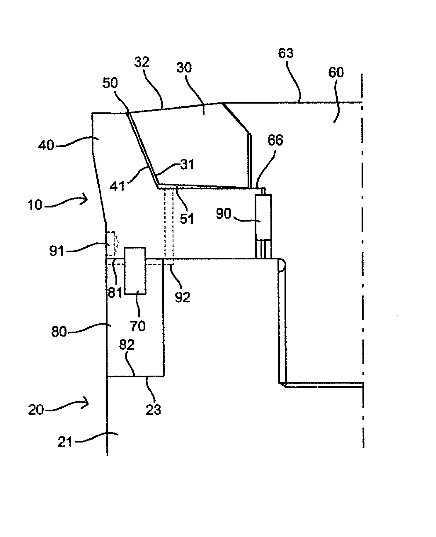
[0065]FIG. 3 shows a schematic half section of the dummy block according to the invention, whereby the connecting element forms a stepped connecting ring 61, and an adapter stud 62 forms part of the pressing surface. Here, the adapter stud 62 can be detachably screwed into the adapter 21 or else can be permanently joined to it or shaped in one piece with the adapter 21. The adapter stud 62 is surrounded by a connecting ring 61 that serves as a connecting element as set forth by the invention, whereby the return force can be transmitted to the sealing ring 40 via this connecting element.
[0066]The return force is preferably transmitted via a step on the circumference of the connecting ring 61 having a radial tensioning surface 66′ that is in contact with the sealing ring 40 when the extrusion ram 20 is retracted together with the adapter stud 62. The return force is transmitted from the adapter stud 62 to the connecting ring 61, for example, by means of a threaded connection, whereas ...
fifth embodiment
[0084]FIG. 6 shows the invention in which the connecting element is a circumferential connecting member 110 that is attached to the extrusion ram 20 or to an adapter piece 21 of the extrusion ram 20. Preferably, this is a continuous ring-shaped connecting member that runs around the longitudinal axis of the dummy block 10, but the connecting member can also be configured so as to be discontinuous in sections. Here, the connecting member is installed on the surface of the adapter piece 21 that faces the sealing ring 40, and it extends into a corresponding circumferential recess 109 that is provided in the sealing ring 40. The connecting member 110 can be configured in one piece with the adapter piece 21 or else as a separate part that can be affixed to the adapter piece.
[0085]The circumferential connecting member 110 and the recess 109 have essentially the same shape, whereby there is a small amount of play between the connecting member 110 and the recess 109 so that the two parts ca...
PUM
| Property | Measurement | Unit |
|---|---|---|
| Force | aaaaa | aaaaa |
| Pressure | aaaaa | aaaaa |
| Distance | aaaaa | aaaaa |
Abstract
Description
Claims
Application Information
 - R&D
- Intellectual Property
- Life Sciences
- Materials
- Tech Scout
- Unparalleled Data Quality
- Higher Quality Content
- 60% Fewer Hallucinations
Browse by: Latest US Patents, China's latest patents, Technical Efficacy Thesaurus, Application Domain, Technology Topic, Popular Technical Reports.
© 2025 PatSnap. All rights reserved.Legal|Privacy policy|Modern Slavery Act Transparency Statement|Sitemap|About US| Contact US: help@patsnap.com