
Electrical harness connector system with differential pair connection link

a technology of electrical connectors and differential pairs, applied in the field of electrical connectors, can solve the problems of reducing assembly efficiency, affecting the safety of electrical connectors, so as to minimize skew and maximize balance

Active Publication Date: 2016-11-15
MOLEX INC
View PDF21 Cites 2 Cited by
  • Summary
  • Abstract
  • Description
  • Claims
  • Application Information

AI Technical Summary

Benefits of technology

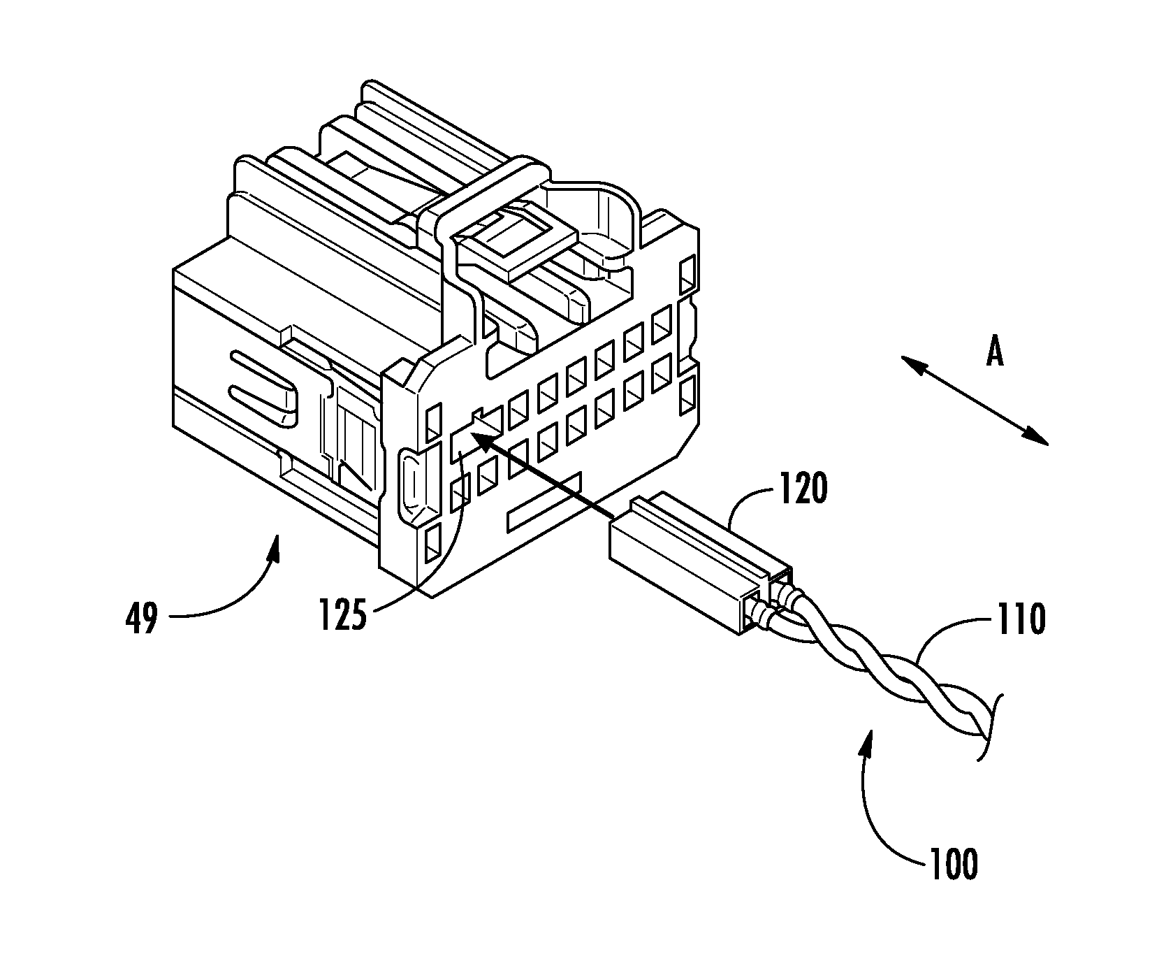
The patent text describes a connector system that allows two terminals to be grouped together before being connected to a chosen termination process. This ensures that wires are pre-twisted at equal points on the cable, reducing interference between them. The system also ensures that each terminal is connected to a separate point on the cable, resulting in a more balanced electrical connection. In some versions of the system, the connectors are designed to prevent debris and moisture from entering through the wires. This creates a tightly-managed, unitized terminated link that is suitable for use in wire harness manufacturing processes.

Problems solved by technology

This approach is seen today with High Speed Controller Area Network and FlexRay technologies, which is labor intensive, as the twisting of the wire is performed after assembly into the connector cavity body and done so with inconsistent twist rate control which affect, inter alia, impedance control and, thereby, performance for higher speed technologies such as Ethernet or LVDS (Low Voltage Differential Signaling).
To further complicate the assembly, each pair of terminals must be attached to the wire leads at both ends before the twist occurs, resulting in the potential imbalance of terminal presentation at the second (final) end of the twisted wire length prior to insertion in the connector.
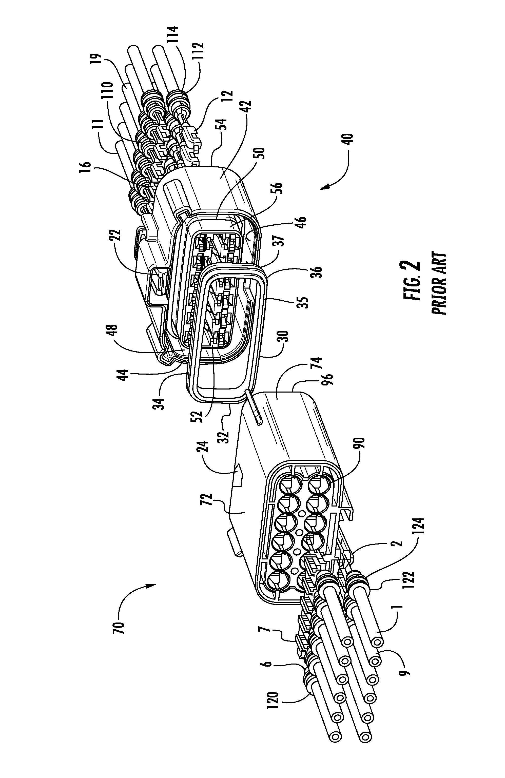
In certain applications, further requirements such as moisture and debris prevention, the addition of seals further complicates this assembly and creates added difficulty in maintaining consistency, resulting in decreased assembly efficiency.

Method used


Image

  • Electrical harness connector system with differential pair connection link
  • Electrical harness connector system with differential pair connection link
  • Electrical harness connector system with differential pair connection link

Examples


Embodiment Construction

[0037]While the Present Disclosure may be susceptible to embodiment in different forms, there is shown in the Figures, and will be described herein in detail, specific embodiments, with the understanding that the Present Disclosure is to be considered an exemplification of the principles of the Present Disclosure, and is not intended to limit the Present Disclosure to that as illustrated.

[0038]As such, references to a feature or aspect are intended to describe a feature or aspect of an example of the Present Disclosure, not to imply that every embodiment thereof must have the described feature or aspect. Furthermore, it should be noted that the description illustrates a number of features. While certain features have been combined together to illustrate potential system designs, those features may also be used in other combinations not expressly disclosed. Thus, the depicted combinations are not intended to be limiting, unless otherwise noted.

[0039]In the embodiments illustrated in ...


PUM


Abstract

An electrical connector system includes a plug connector and a receptacle connector, each of which include a plurality of terminal receiving cavities for receiving a plurality of terminal lead wires. The electrical connector system further includes a connector link comprising a twisted pair differential cable for providing a data rate high data rate signal transmission transfer with the connector system, in addition to standard power and signal transmission, wherein the connector link is modularly connected within the electrical connector system.

Description

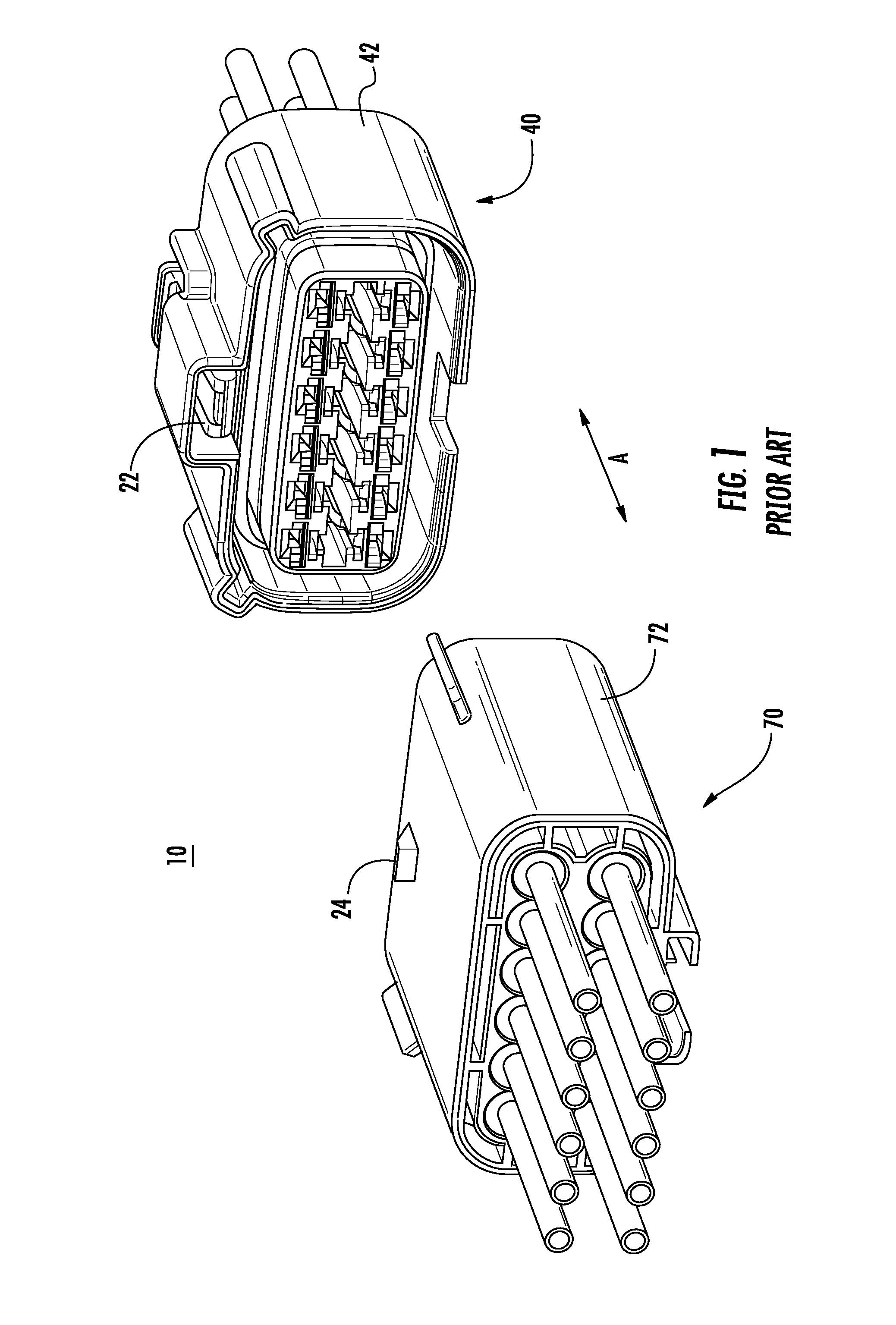
REFERENCE TO RELATED APPLICATIONS[0001]The Present Disclosure claims priority to prior-filed U.S. Provisional Patent Application No. 61 / 674,466, entitled “Differential Pair Link For Ethernet Automotive Harness Wiring,” filed on 23 Jul. 2012 with the United States Patent And Trademark Office. The content of the aforementioned Patent Application is incorporated in its entirety herein.BACKGROUND OF THE PRESENT DISCLOSURE[0002]The Present Disclosure relates generally to the field of electrical connectors. In particular, the Present Disclosure relates to multi-conductor shielded and unshielded electrical connectors used in cable harnesses.[0003]Today, traditional wire harness manufacturing presents a plurality of “single wires” terminated to a terminal. As is best illustrated in FIG. 1, a plurality of such single terminated wires are arranged and combined to form a bundled wire harness. In many instances, certain applications require high data rate transfer and use of a balanced, or impe...

Claims


Application Information

Patent Timeline
Patent Type & Authority Patents(United States)
IPC IPC(8): H01R31/06H01R13/518H01R13/6463H01R13/52H01R9/03H01R13/6581H01R13/514
CPCH01R31/06H01R9/035H01R13/514H01R13/518H01R13/5208H01R13/6463H01R13/6581H01R13/65915
Inventor GARDNER, MICHAEL J.
Owner MOLEX INC
Learn More