
Method and vessel for laying a pipeline

a pipeline and stinger technology, applied in the direction of pipe laying vessels, pipe laying and repair, mechanical equipment, etc., can solve the problems of increasing the difficulty of weathervaning, increasing the difficulty of laying, and the path followed by the pipeline from the downstream end of the stinger to the point at which the pipeline touches down on the seabed inevitably changes substantially, so as to achieve the effect of simple construction and robustness and economic benefits

Active Publication Date: 2016-11-22
SAIPEM SPA
View PDF49 Cites 0 Cited by
  • Summary
  • Abstract
  • Description
  • Claims
  • Application Information

AI Technical Summary

Benefits of technology

[0019]Each guide for limiting lateral movement of the pipeline preferably extends on one side or another of the pipeline and defines a lateral guide. Each lateral guide preferably comprises a roller mounted for rotation about an axis disposed in a respective vertical plane and substantially perpendicular to the pipelaying path in the vicinity of the roller. The axis of rotation of the roller may be adjustable during laying of the pipeline but for simplicity it is preferably fixed during laying. It is however preferred that the axis can be adjusted laterally prior to laying of the pipeline. That provides a more versatile arrangement.
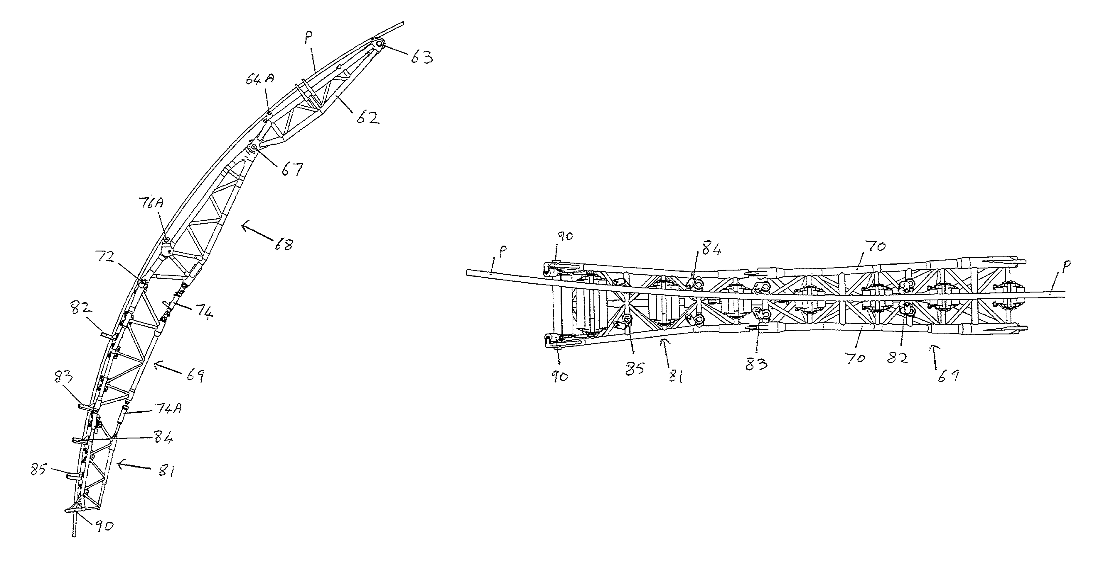
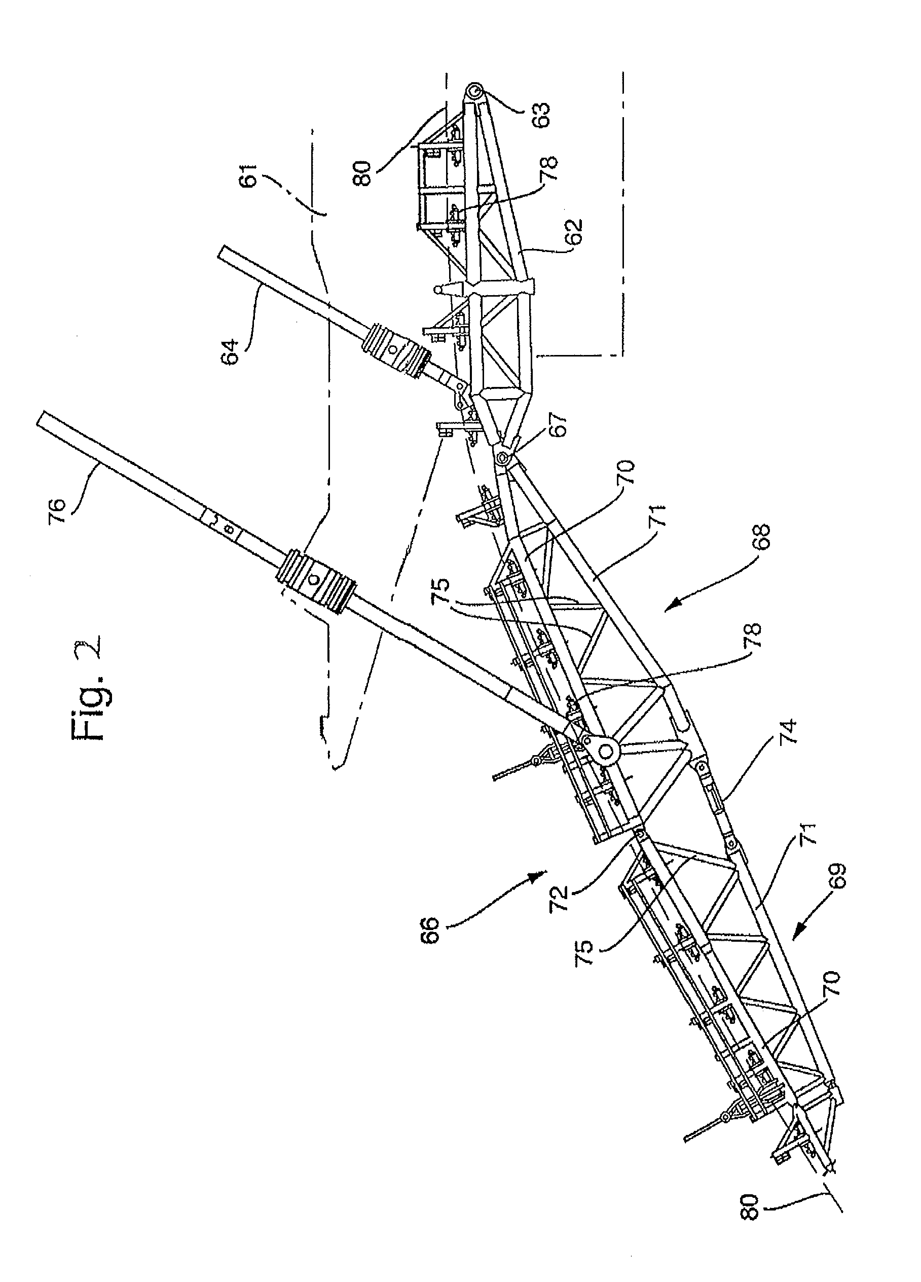
[0029]The stinger preferably comprises a series of sections that are pivotally adjustable relative to one another about a horizontal axis to alter the overall downward inclination of the stinger along its length but are fixed against pivotal movement about an axis in a vertical plane and perpendicular to the path of the pipeline in that region of the stinger. By providing such limited pivoting of the stinger sections it becomes possible to provide a robust and economical stinger which is especially suited to use when the vessel is weathervaning. It might be thought that, in order to allow weathervaning, it would be particularly desirable to allow the stinger itself to pivot or curve laterally, especially bearing in mind that any lateral force on the downstream end of a stinger will apply a substantial torque at the connection of the stinger to the vessel and at any intermediate pivot connections that allow only pivoting in a vertical plane. We have found, however, that it is feasible to provide a stinger and vessel able to resist such torques and that the construction can be kept much simpler by not providing for any lateral movement. We have found that an especially good solution is to provide a stinger which is itself restricted to movement in a vertical plane, and to allow the pipeline to follow a curved path on the stinger and occupy a position offset from a central portion of the stinger.

Problems solved by technology

When that occurs, it may be necessary to cease pipelaying, but that is undesirable.
The generally shallower inclination of the pipeline as it leaves the stinger makes any such weathervaning a much more challenging prospect.
There is, however, then still a problem that, if the orientation of the vessel is rotated to face in a direction inclined to the pipelaying path, then the path followed by the pipeline from the downstream end of the stinger to the point at which the pipeline touches down on the seabed inevitably changes substantially and becomes complex.
This arrangement avoids the problem referred to above with conventional S-laying but can only be employed in relatively deep water

Method used


Image

  • Method and vessel for laying a pipeline
  • Method and vessel for laying a pipeline
  • Method and vessel for laying a pipeline

Examples


Embodiment Construction

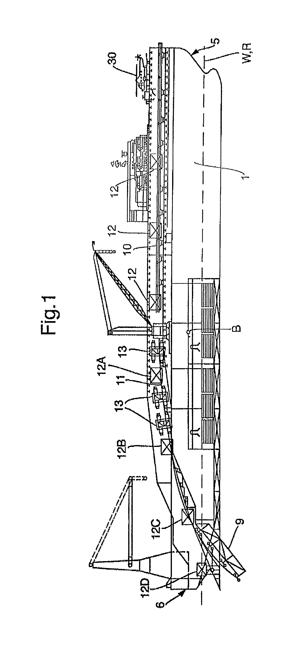
[0049]FIG. 1 is the same drawing as shown in WO 2008 / 107186 and reference can be had to that publication for further details of that vessel. Since, however, embodiments of the invention described below comprise modifications of the vessel shown in the drawings of WO 2008 / 107186 it is convenient to describe briefly the vessel shown in that publication the contents of which are incorporated herein by reference.

[0050]The vessel generally comprises a vessel hull 1, within which are defined a plurality of prefabricated decks for the prefabrication of jointed pipe sections from individual lengths of pipe and on which cranes and other facilities are provided. The bow 5 of the hull 1 is shown on the right hand side and the stern 6 of the hull 1 is shown on the left hand side, as viewed in FIG. 1.

[0051]The vessel hull 1 is of unconventional design at its stern end, having starboard and port end portions between which an elongate recess is defined. The recess is open at the stern end of the h...


PUM


Abstract

A stinger extends away from an end of a vessel, and a pipeline passes over the stinger as the pipeline is laid from the vessel. The inclination of the pipeline increases as the pipeline passes along the stinger and after leaving the stinger until the pipeline reaches an inflection point beyond the end of the stinger at which inclination is at a maximum. Inclination of the pipeline thereafter reduces until the pipeline touches down on the seabed. A method of S-laying the pipeline includes providing guides on the stinger that limit lateral movement of the pipeline relative to the stinger and moving the vessel and the stinger during S-laying to an orientation in which the longitudinal axis of the stinger is inclined to the path of the pipeline just laid. The vessel and the stinger are rotated about a vertical axis passing through or adjacent to the inflection point.

Description

BACKGROUND OF THE INVENTION[0001]This invention relates to a method of laying a pipeline and to a pipelaying vessel. Such methods and vessels are of particular use in the offshore industry relating to oil and gas production.[0002]One of the tasks that is carried out by certain vessels in the offshore industry is that of laying pipelines, either by S-laying or by J-laying.[0003]In S-laying, the pipeline leaves the vessel at little or no inclination to the horizontal, adopts a steeper inclination in the water and then returns to a generally horizontal disposition on the seabed. The tension in the pipeline is often accommodated by a series of track tensioners mounted along the pipelaying path, on the vessel. The track tensioners support the weight of the pipeline and control passage of the pipeline. To allow S-laying a stinger may be provided, extending away from an end of the vessel with the pipeline passing over the stinger as it is laid from the vessel and increasing in its inclinat...

Claims


Application Information

Patent Timeline
Patent Type & Authority Patents(United States)
IPC IPC(8): F16L1/18B63B35/03F16L1/225
CPCF16L1/18B63B35/03F16L1/225
Inventor BIANCHI, STEFANOBRUSCHI, ROBERTOLAZZARIN, DIEGO
Owner SAIPEM SPA
Learn More