
System for reading photo-stimulated accumulative luminescent substances

a luminescent substance and photo-stimulated technology, applied in the field of photostimulated luminescence, can solve the problems of increasing the time required for exposure and development, time-consuming and expensive to first expose and then develop x-ray films, and increasing the cost of the whole arrangemen

Inactive Publication Date: 2002-12-31
FRAUNHOFER GESELLSCHAFT ZUR FOERDERUNG DER ANGEWANDTEN FORSCHUNG EV
View PDF10 Cites 0 Cited by
  • Summary
  • Abstract
  • Description
  • Claims
  • Application Information

AI Technical Summary

Benefits of technology

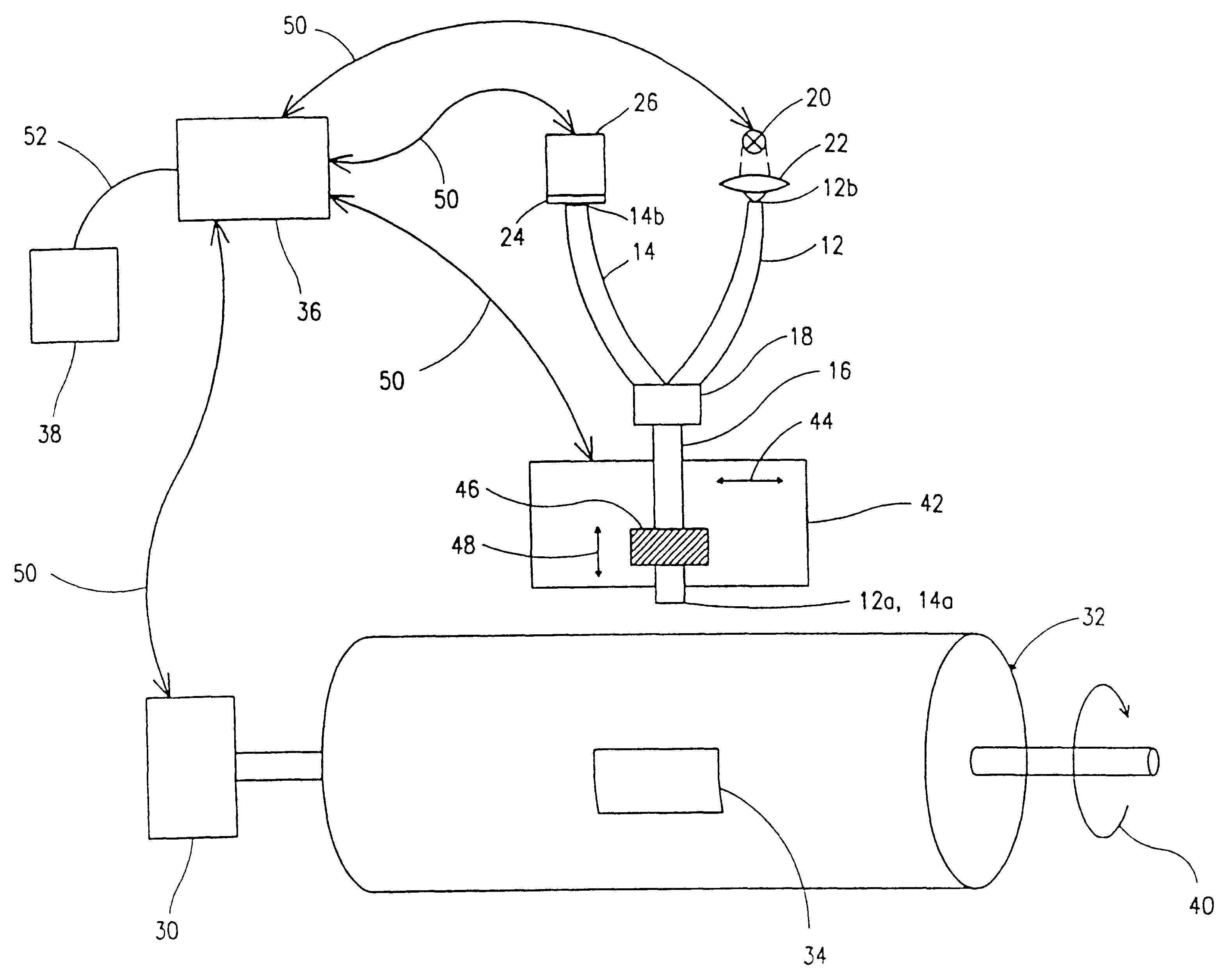
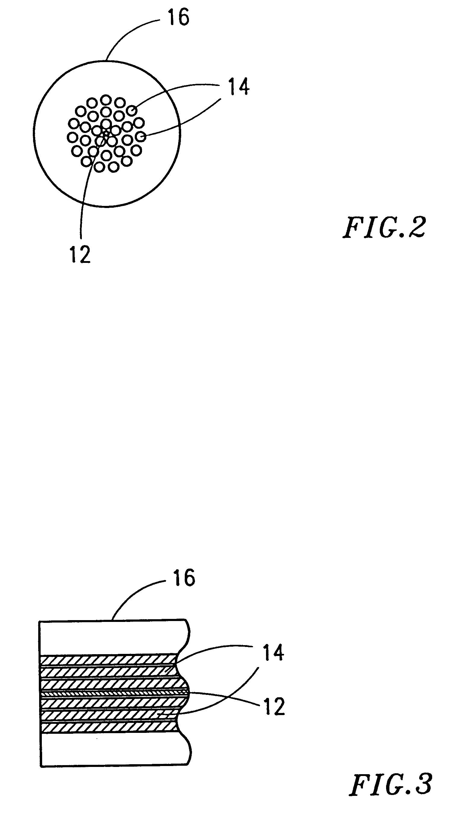
The present invention is based on the finding that it is possible to achieve a more robust and more economical glass fibre drum scanner by dispensing with the optics for focusing the excitation light and for receiving the excited light so as to achieve a readout with high resolution and high contrast. The optics for focusing and for receiving the excited light can the more readily be dispensed with if a glass fibre with a small numerical aperture is used for the excitation glass fibre, whereas, by contrast, the receiving glass fibre must be a glass fibre with a large numerical aperture. The numerical aperture is known to specialists and is equal to the sine of half the solid angle of a maximum radiation cone which can be supplied by a glass fibre or which can be fed into a glass fibre. For a graded-index fibre e.g. the numerical aperture is calculated from the square root of the difference between the mean refractive indices of the glass fibre sheath and the glass fibre core. In accordance with the present invention the excitation fibre therefore consists of a glass fibre with a small numerical aperture, whereby the excitation light cone which it produces has a small solid angle, which means that, for a still moderate separation of the end of the excitation glass fibre which is positioned near the storage luminescent substance, a sufficient spot size is attainable, which in the final analysis defines the resolution with which the previously exposed storage luminescent substance foil can be read. By contrast, the receiving glass fibre, i.e. the glass fibre which collects the light emitted due to photoluminescence, must have a large numerical aperture, greater at least than the numerical aperture of the excitation glass fibre, in order that as much as possible of the light released due to photoluminescence can be collected. To increase the amount of photoluminescent light which is detected, and thus increase the sensitivity of a scanner, a multiplicity of receiving glass fibres may for preference be arranged around the excitation glass fibre, it being obvious to persons skilled in the art that the numerical aperture of a receiving glass fibre of the multiplicity of receiving glass fibres may then be smaller than the numerical aperture of a single receiving glass fibre while still achieving sufficient sensitivity of the storage luminescent substance scanner.

Problems solved by technology

It is time consuming and expensive to first expose and then develop X-ray films, the time needed for exposure and development being in general considerably greater than the time spent in actually looking at the X-ray picture in order to make a diagnostic decision.
This focusing / imaging lens, which has to serve both to focus the exciting light and to collect the light created by photoluminescence, makes the whole arrangement more expensive, since it must not only be fabricated but it must also be positioned and adjusted.
As a result the receiving glass fibre provides relatively good transmission conditions for the light emitted by a phosphor layer whereas it provides relatively poor transmission conditions for the light for exciting the phosphor, this light having a longer wavelength than the phosphorescent light emitted by the phosphor layer, whereby the glass fibre acts roughly like a high-pass filter.

Method used


Image

  • System for reading photo-stimulated accumulative luminescent substances
  • System for reading photo-stimulated accumulative luminescent substances
  • System for reading photo-stimulated accumulative luminescent substances

Examples


Embodiment Construction

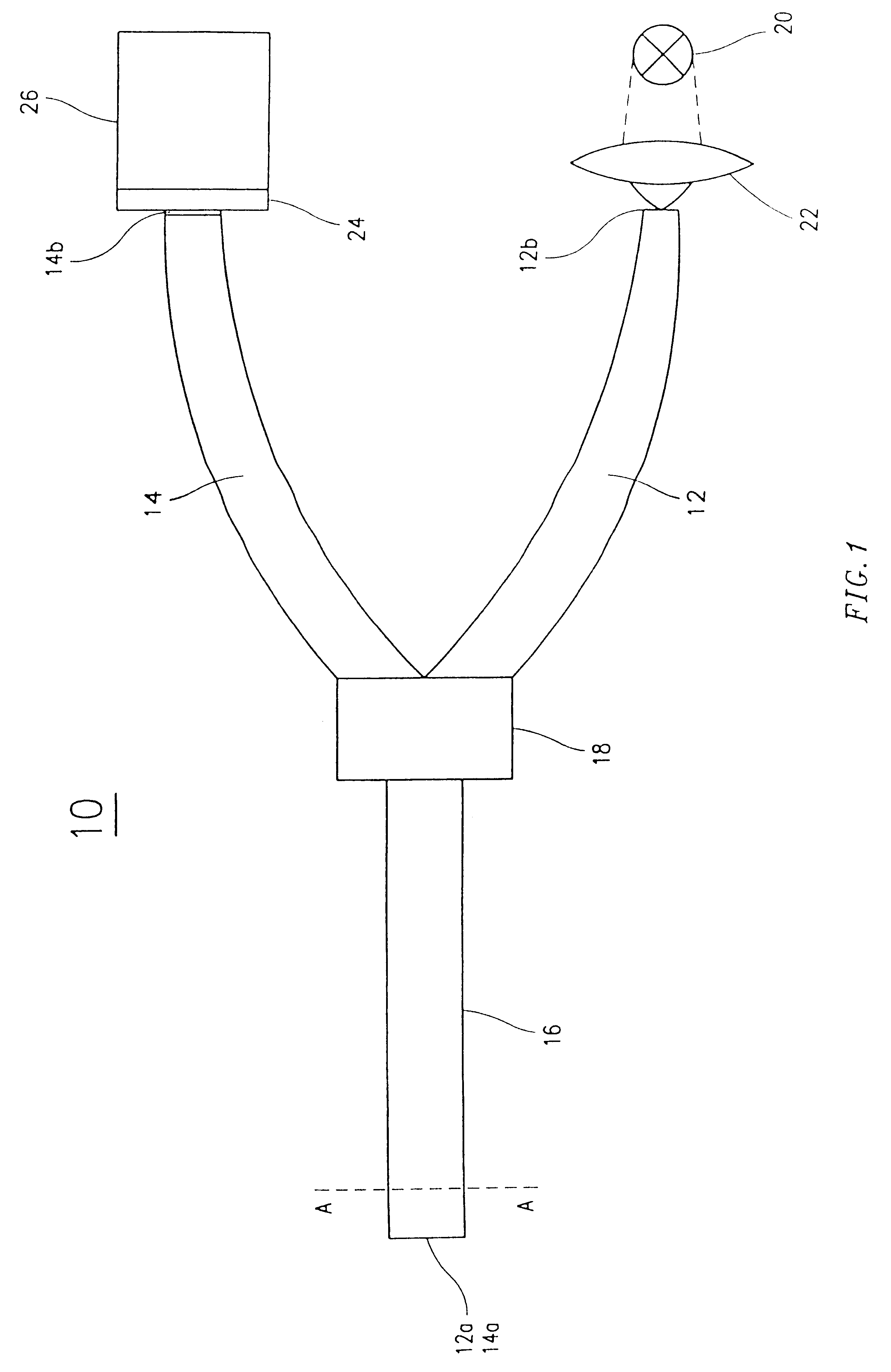
FIG. 1 shows an arrangement 10 for reading photo-stimulable storage luminescent substances according to the present invention. The arrangement 10 comprises an excitation glass fibre 12 and a receiving glass fibre 14, one end 12a and one end 14a being arranged in close proximity to each other in a region which can be positioned near a photo-stimulable storage luminescent substance. In the region of the one ends 12a and 14a the excitation glass fibre 12 and the receiving glass fibre 14 thus form a common bundle 16, which is split into the receiving glass fibre 14 and the excitation glass fibre 12 at a crossover section 18. The other end 12b of the excitation glass fibre is positioned near a light source 20 by means of which light can be fed into the excitation glass fibre 12, which has a small numerical aperture, via a suitable lens 22.

The other end 14b of the receiving glass fibre, which has a large numerical aperture compared with the numerical aperture of the excitation glass fibre...


PUM


Abstract

An arrangement for reading photo-stimulable storage luminescent substances comprises an excitation glass fiber into which light which excites the storage luminescent substance can be fed by means of a light source. Light emitted by the excited storage luminescent substance can be fed into a receiving glass fiber, an end of the excitation glass fiber which is positioned close to the storage luminescent substance being arranged next to an end of the receiving glass fiber which can be positioned close to the storage luminescent substance. The excitation glass fiber (12) has a first numerical aperture and the receiving glass fiber has a second numerical aperture which is large compared with the first numerical aperture, as a result of which the light fed out from the excitation glass fiber is directed straight onto the storage luminescent substance without an optical arrangement and the stimulated light can be captured by the receiving glass fiber without an optical arrangement. A glass fiber drum scanner uses the arrangement for reading photo-stimulable storage luminescent substances to achieve a two-dimensional readout of the storage luminescent substance by means of an advancing device which moves the one ends of the excitation glass fiber and the receiving glass fiber in one direction and by means of a rotary drum to which the storage luminescent substance is attached.

Description

The present invention relates generally to optical scanners and in particular to a device for reading photo-stimulable storage luminescent substances.BACKGROUND OF THE INVENTION AND PRIOR ARTThe present invention uses the effect of photo-stimulated luminescence. Phosphorus is one example of the substances which display photoluminescence. A storage luminescent substance, e.g. one which contains phosphorus, absorbs radiation energy, which excites electrons into higher energy states. These higher energy states are unstable, so that the phosphor electrons fall back into a state with lower energy, the energy difference being emitted as light. The emitted light energy typically has a different wavelength than the radiation energy which has induced the photoluminescence.In the field of dental medicine in particular, in which a plurality of X-ray pictures is created, there is a great need to replace the traditional X-ray pictures with new imaging techniques. It is time consuming and expensi...

Claims


Application Information

Patent Timeline
Patent Type & Authority Patents(United States)
IPC IPC(8): G01T1/00G01T1/29G03B42/02G03B42/00
CPCG01T1/2014
Inventor SCHRECK, OLIVERHANKE, RANDOLF
Owner FRAUNHOFER GESELLSCHAFT ZUR FOERDERUNG DER ANGEWANDTEN FORSCHUNG EV
Learn More