Electrical plug connector and electrical receptacle connector

a technology of electrical receptacles and plug connectors, which is applied in the direction of coupling devices, two-part coupling devices, electrical apparatus, etc., can solve the problems of reducing the signal transmission quality, electromagnetic waves which interfere with the functions and signal transmission of electrical devices, etc., and achieve the effect of reducing emi and rmi problems

Active Publication Date: 2016-11-22
ADVANCED CONNECTEK INC
View PDF27 Cites 22 Cited by
  • Summary
  • Abstract
  • Description
  • Claims
  • Application Information

AI Technical Summary

Benefits of technology

[0009]As above, in the electrical plug connector of the disclosure, the arm portions are connected to the metal shell, and the soldering portions of the buckling members are connected to one circuit board; while in the electrical receptacle connector of the disclosure, the soldering portions of the grounding sheet are connected to another circuit board. Consequently, low-impedance grounding path can be provided upon the electrical plug connector being connected with the electrical receptacle connector, thereby reducing the EMI and RMI problems. Additionally, the soldering portions of the buckling members are soldered on the circuit board to provide the structural strength of the buckling members. Additionally, because the upper-row terminals and the lower-row terminals are arranged upside down, and the arrangement sequence of the upper-row plate contacts are left-right reversal with respect to the arrangement sequence of the lower-row plate contacts, an electrical plug connector is inserted into the interior of the electrical receptacle connector with the terminals of the electrical plug connector contacting with the upper-row plate contacts when plugged in a forward orientation, and the electrical plug connector is inserted into the interior of the electrical receptacle connector with the terminals of the electrical plug connector contacting with the lower-row plate contacts when plugged in a reverse direction. Consequently, the inserting orientation of the electrical plug connector is not limited.

Problems solved by technology

Current electrical devices have multiple functions to provide significant convenience for people; however, electromagnetic waves which interfere with the functions and the signal transmissions of the electrical devices, are generated upon operating the electrical devices; for example, electromagnetic interference (EMI) or radio frequency interference (RFI).
The conventional USB electrical receptacle connector and the conventional USB electrical plug connector induce signal interference, such as EMI, RFI, etc., upon transmitting signals, resulting in reduction of signal transmission quality.

Method used


Image

  • Electrical plug connector and electrical receptacle connector
  • Electrical plug connector and electrical receptacle connector
  • Electrical plug connector and electrical receptacle connector

Examples


Embodiment Construction

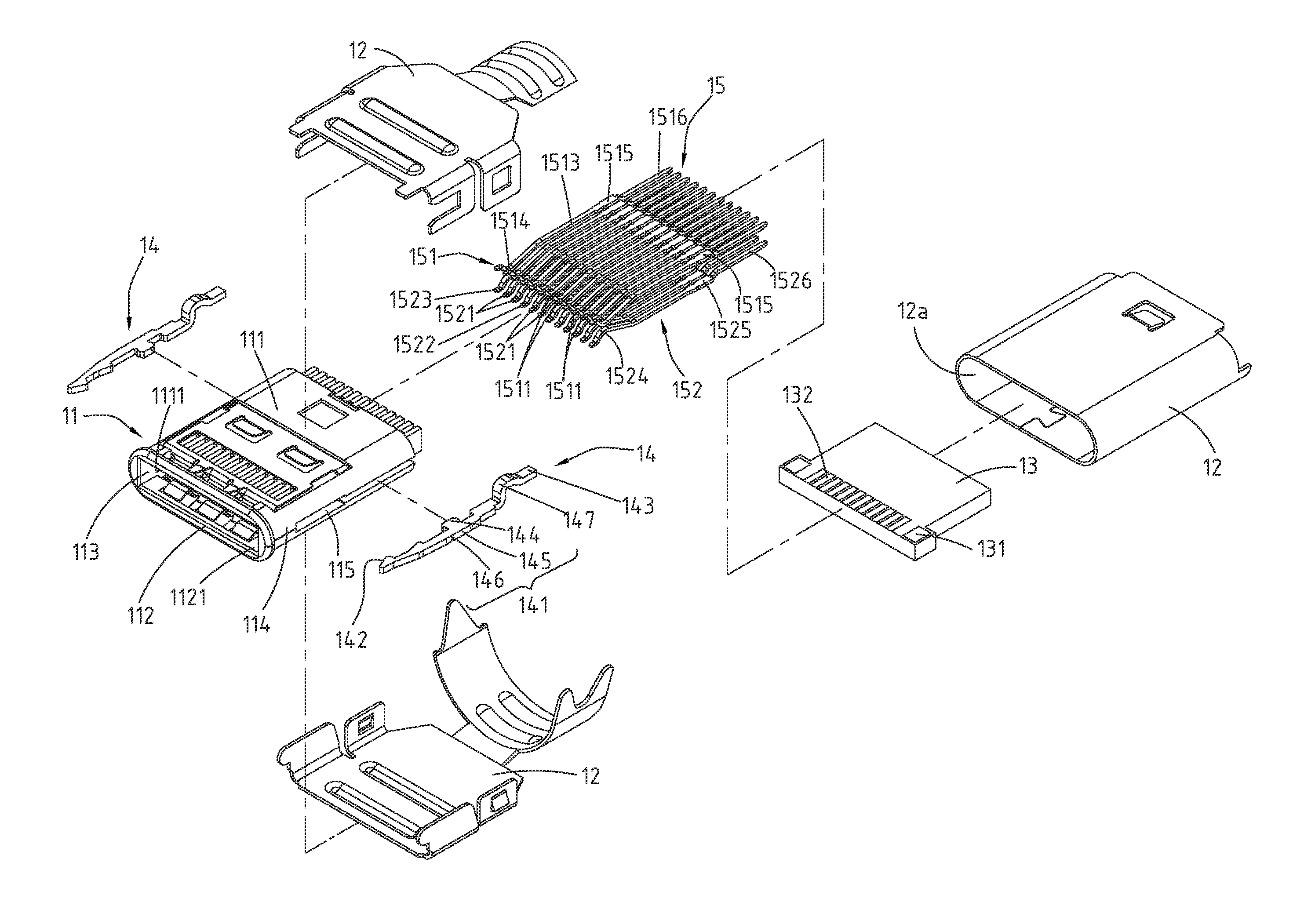
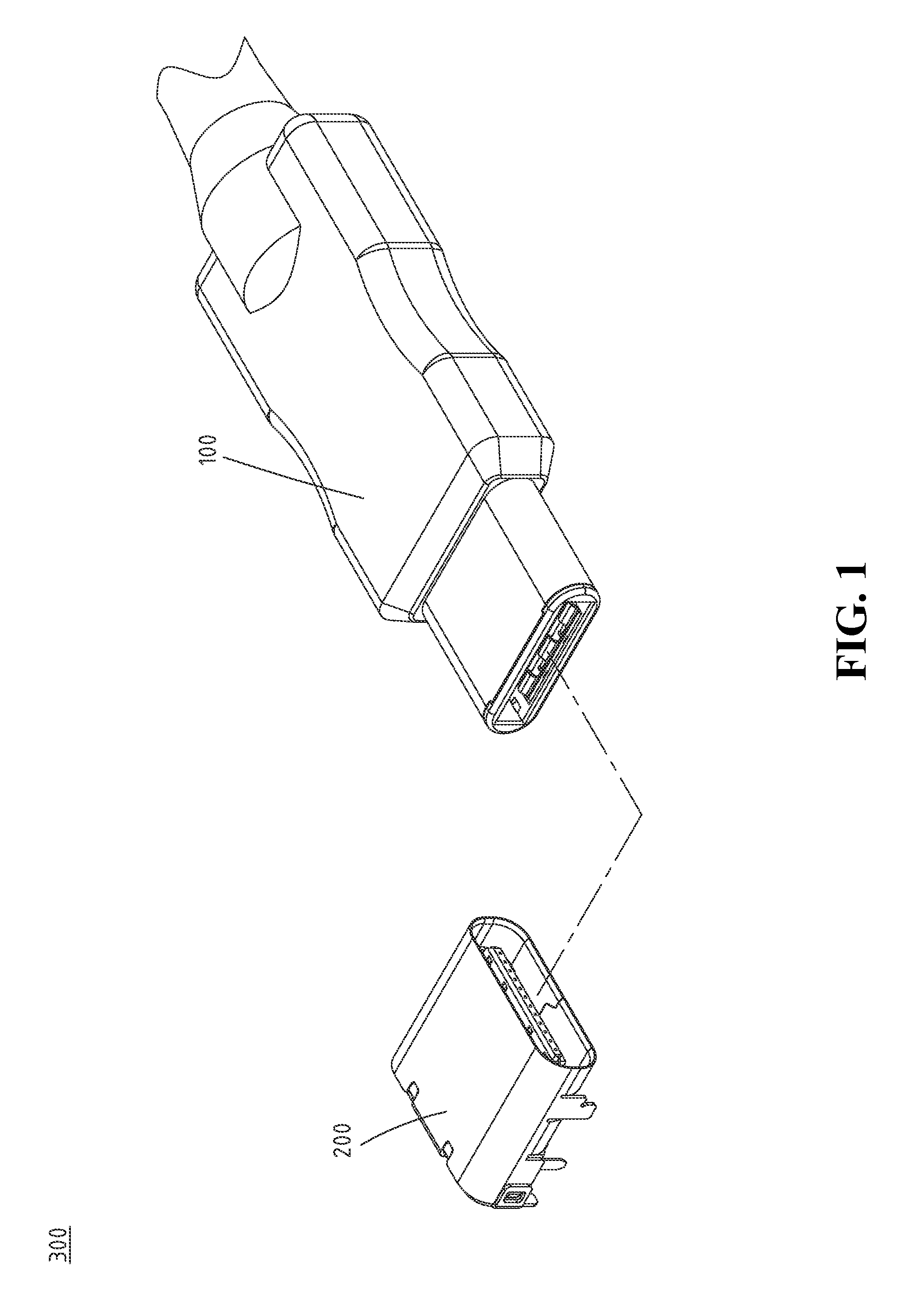
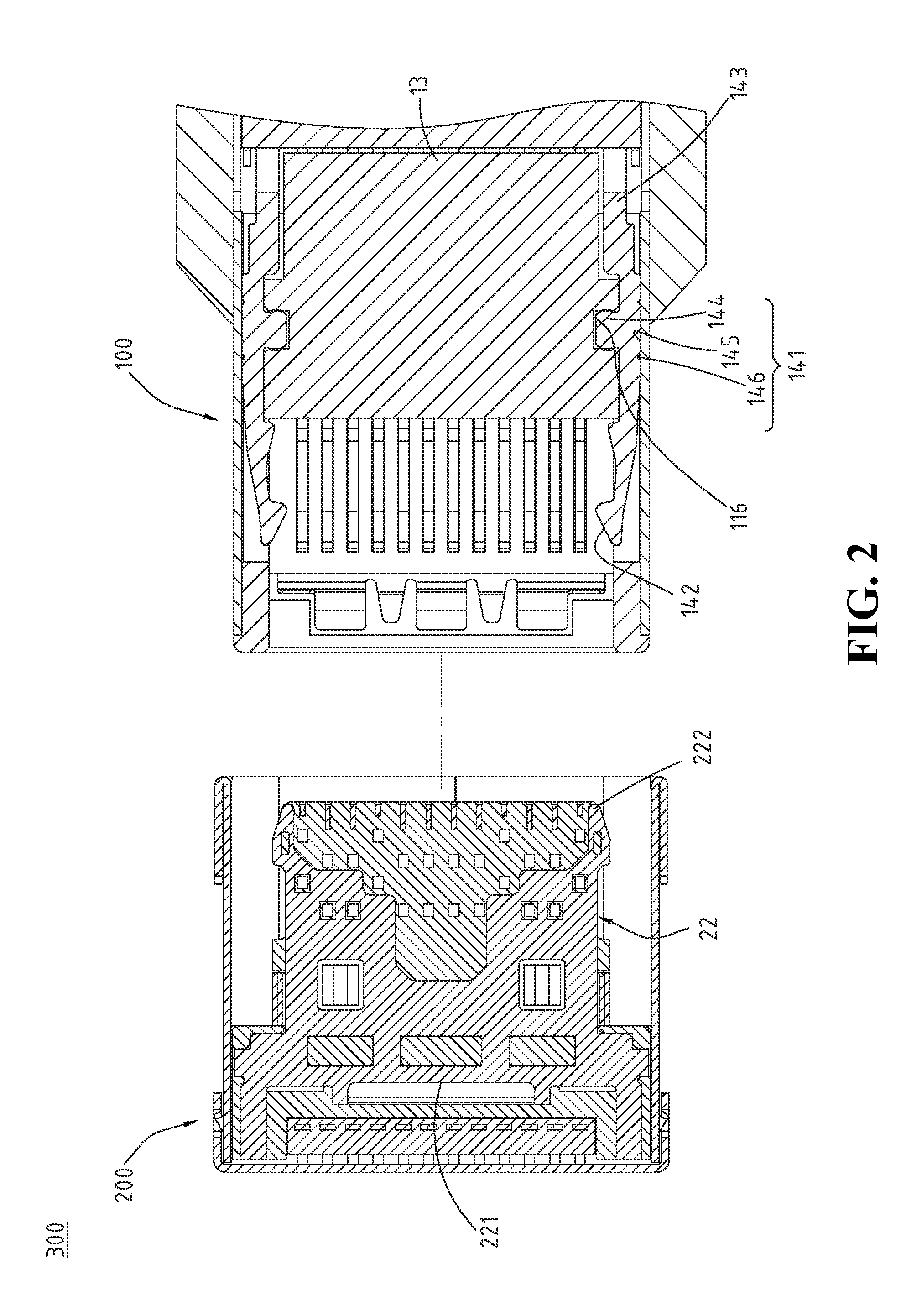
[0030]Please refer to FIG. 1, FIG. 2 and FIG. 3, in which an electrical connector assembly 300 of the disclosure is illustrated; FIG. 1 is an exploded view showing an electrical plug connector 100 and an electrical receptacle connector 200 of the electrical connector assembly 300, and FIG. 2 and FIG. 3 are top sectional views respectively showing the electrical plug connector 100 is detached from or assembled with the electrical receptacle connector 200. The electrical connector assembly 300 includes an electrical plug connector 100 and an electrical receptacle connector 200.

[0031]Please refer to FIG. 4, FIG. 5 and FIG. 6, in which an electrical plug connector 100 of a first embodiment of the disclosure is illustrated. FIG. 4 is an exploded view (1) of the electrical plug connector 100, FIG. 5 is a lateral view of the electrical plug connector 100 of the disclosure while the metal shell 12 is eliminated from the electrical plug connector 100, and FIG. 6 is a perspective view of the ...


PUM


Abstract

An electrical plug connector includes an insulation housing, a metal shell and plural buckling members. The insulation housing includes an insertion cavity, plural lateral sides and plural assembling spaces. The insertion cavity is disposed at a front portion of the insulation housing. The lateral sides are disposed at two sides of the insulation housing. The assembling spaces are disposed at the lateral sides and communicate with the insertion cavity. The metal shell encloses the insulation housing. The buckling members are respectively disposed in the assembling spaces and each includes a arm portion, a hook portion and a soldering portion. The arm portion is disposed in the assembling portion, the hook portion is extended from a front portion of the arm portion toward the insertion cavity, and the soldering portion is extended from a rear portion of the arm portion and exposed out of the assembling space.

Description

CROSS-REFERENCES TO RELATED APPLICATIONS[0001]This non-provisional application claims priority under 35 U.S.C. §119(a) on Patent Application No. 103208542 and 103136076, filed in Taiwan, R.O.C. on 2014 May 15 and 2014 Oct. 17, the entire contents of which are hereby incorporated by reference.FIELD OF THE INVENTION[0002]The disclosure relates to an electrical connector, and particularly to an electrical plug connector and an electrical receptacle connector.BACKGROUND OF THE INVENTION[0003]Current electrical devices have multiple functions to provide significant convenience for people; however, electromagnetic waves which interfere with the functions and the signal transmissions of the electrical devices, are generated upon operating the electrical devices; for example, electromagnetic interference (EMI) or radio frequency interference (RFI).[0004]USB, universal serial bus, is a common electrical connector interface applied to electrical devices; the USB 2.0 interfaces have been furth...

Claims


Application Information

Patent Timeline
Patent Type & Authority Patents(United States)
IPC IPC(8): H01R24/60H01R13/6596H01R13/6581H01R13/6597H01R12/72H01R107/00
CPCH01R24/60H01R12/724H01R13/6581H01R13/6596H01R13/6597H01R2107/00
Inventor KAO, YA-FENTSAI, YU-LUNHOU, PIN-YUANWANG, WEN-YUTSAI, WEN-HSIENLIAO, CHUNG-FU
Owner ADVANCED CONNECTEK INC
Why Eureka
Try Eureka