Modular flooring device and system

a technology of modular flooring and roadway mats, applied in the direction of flooring, single unit paving, walkways, etc., can solve the problems of insufficient strength and ruggedness of light pedestrian grade modular mats for industrial sites, inadequate or incorrect flooring for at least some of the desired applications

Inactive Publication Date: 2016-11-29
SIGNATURE SYST GRP LLC
View PDF84 Cites 36 Cited by
  • Summary
  • Abstract
  • Description
  • Claims
  • Application Information

AI Technical Summary

Benefits of technology

[0011]Each mat also includes a plurality of traction elements disposed on the outer surfaces of the mats. One side of the mat may have industrial grade traction elements for facilitating the moving of heavy duty loads across the flooring system. The opposite side of the mat may have pedestrian grade traction elements for ease and safety of pedestrian foot traffic.

Problems solved by technology

The heavier duty mats needed for industrial use are often too heavy and cumbersome for use in pedestrian applications, and the lighter pedestrian grade modular mats are insufficient in strength and ruggedness for an industrial site.
Existing modular flooring systems use one or the other grade of mat, and therefore are faced with inadequate or incorrect flooring for at least some of the desired applications.
This is not only inconvenient, but can lead to safety and liability issues.
Because of the high costs associated with operations in remote areas, installation and removal of modular floor mats must be accomplished quickly.
This requires a number of connecting parts to also be hauled to the operation site, and if there are not an even number of parts, then insufficient numbers of connections may be made.

Method used


Image

  • Modular flooring device and system
  • Modular flooring device and system
  • Modular flooring device and system

Examples


Embodiment Construction

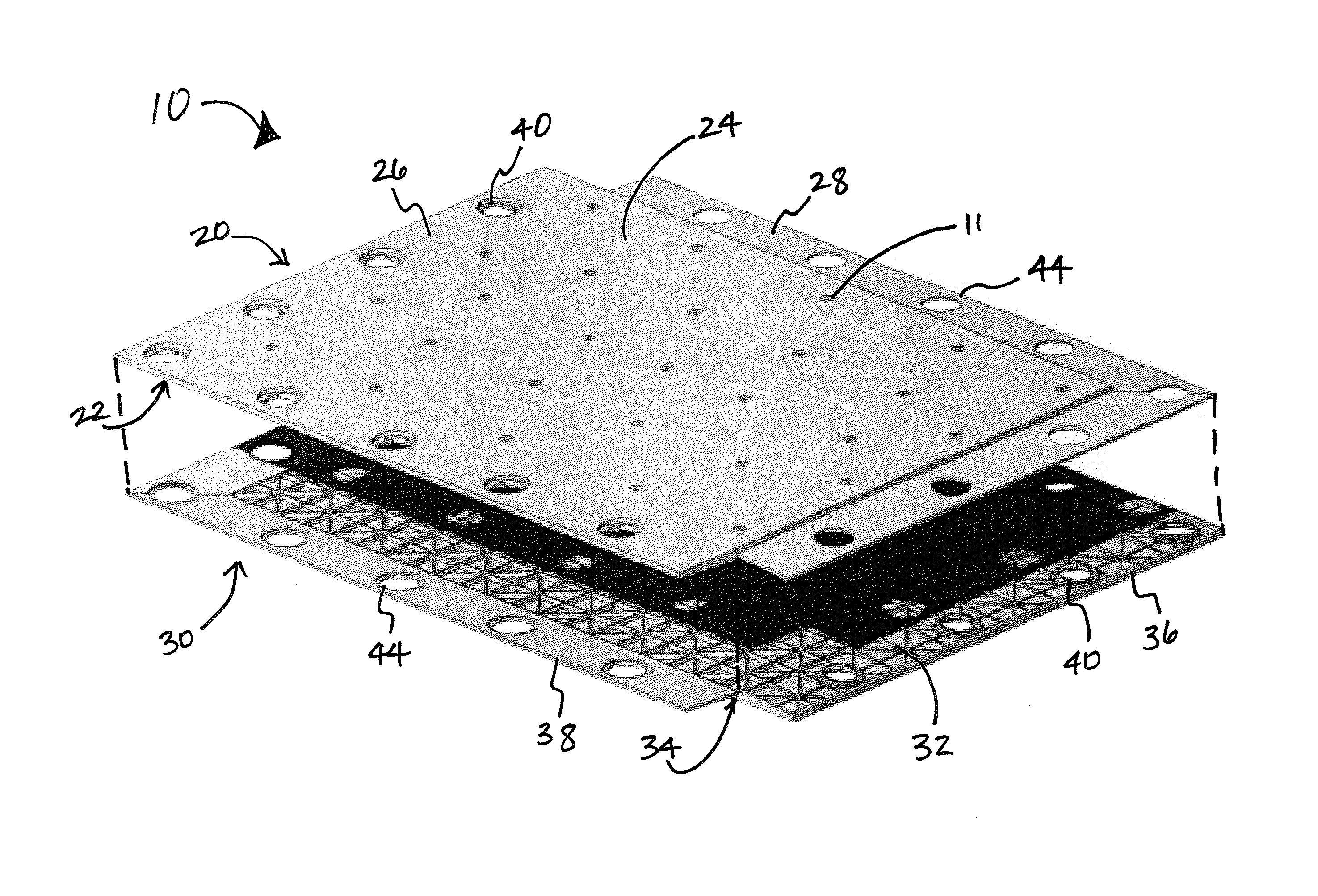
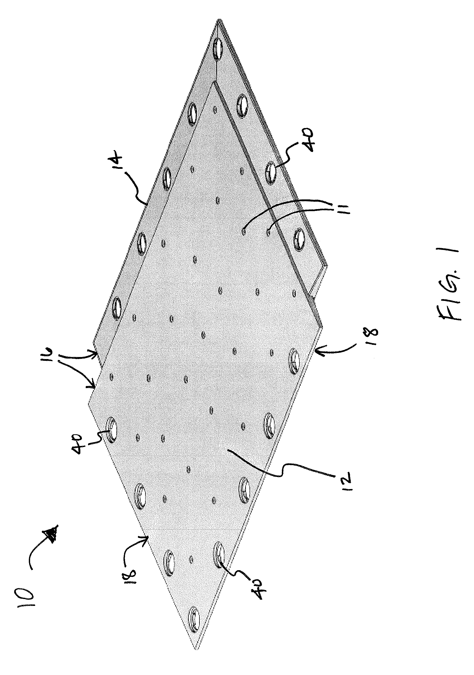
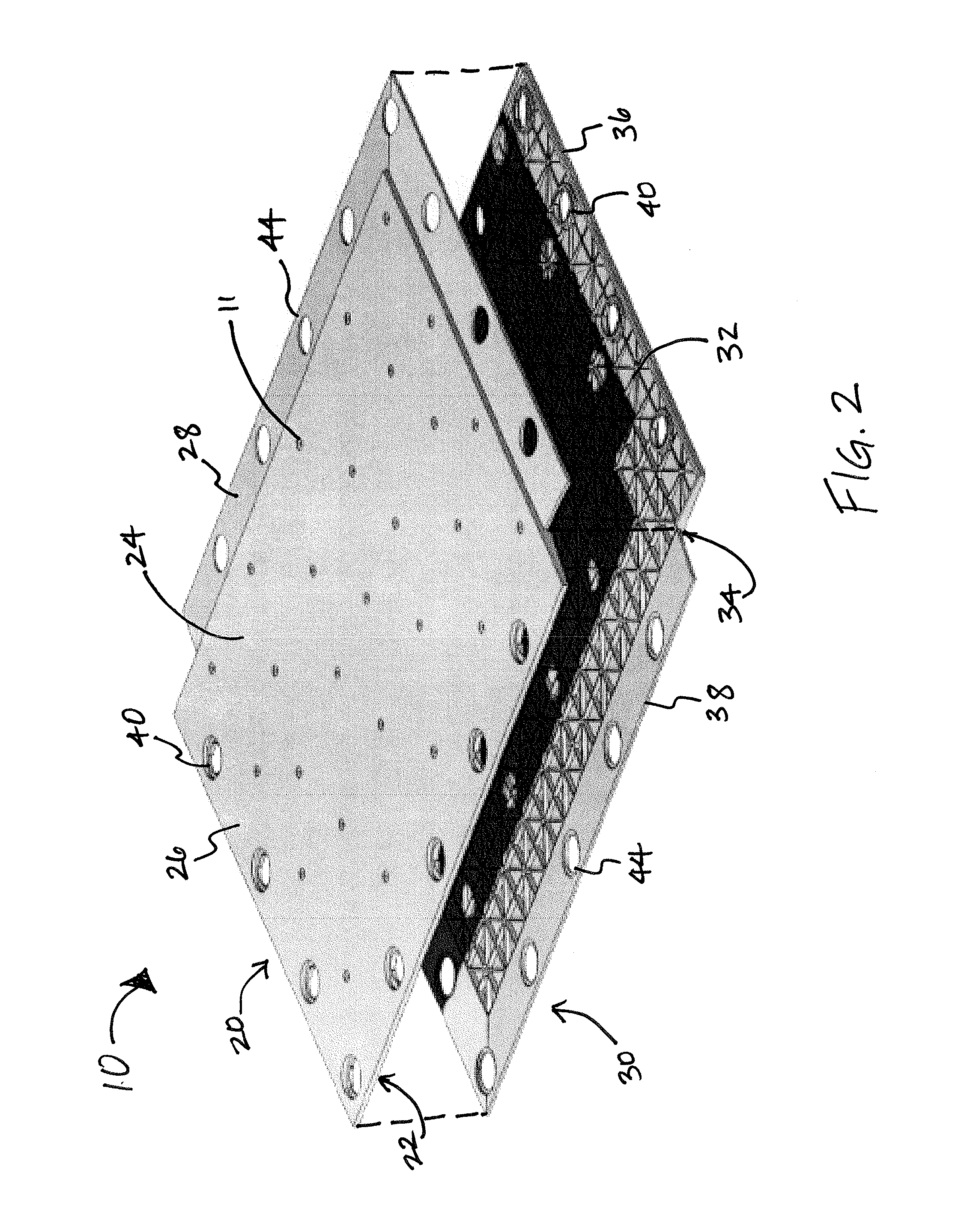
[0039]As shown in the accompanying drawings, the present invention is directed to a modular mat 10 for a floor covering and system 100 comprised of a plurality of such modular floor mats 10. As shown throughout the Figures, and with particular reference to FIGS. 1-4, the modular mat 10 of the present invention is comprised of dual layers which, when affixed together, are entirely congruent with each other and produce no offset portion. The two opposing layers of the mat 10 may further provide a dual surface, having different surface patterns to support both heavy weight, industrial applications, such as equipment, as well as less demanding loads, such as personnel or pedestrians. The mat 10 may be of any suitable dimension that renders the building of a temporary floor covering system, as described further herein. In at least one embodiment, each mat 10 measures approximately 10 feet long by 7.5 feet wide, although it should be understood that any suitable dimensions may be used.

[00...


PUM

PropertyMeasurementUnit
movementaaaaaaaaaa
thicknessaaaaaaaaaa
reinforcing structureaaaaaaaaaa

Abstract

A modular mat comprises mirror image layers. At least one fitting receiver is integrally formed in a central portion of each layer, and at least one aperture is formed in a flange portion of each layer. The layers are congruently mated and affixed such that the fitting receiver of one layer is disposed through a corresponding aperture of the flange of the opposite layer. The outer surfaces of the layers comprise traction elements, which may be of different grades, such as industrial grade on one layer and pedestrian grade on the opposing layer. A floor covering system is also disclosed comprising a plurality of modular mats disposed in partially overlapping and interlocking relation with adjacent mats.

Description

BACKGROUND OF THE INVENTION[0001]Field of the Invention[0002]This invention relates to modular flooring and roadway mats and systems. More in particular, it relates to dual-sided modular floor mats of uniform construction for ease of installation, durability, strength and use in industrial applications.[0003]Description of the Prior Art[0004]Modular flooring systems of various designs have been utilized for a significant period of time to provide a temporary and rigid surface in remote or inaccessible areas. Such systems are primarily utilized in settings where a firm and stable surface is temporarily needed, such as industrial or construction areas. With respect to industrial or construction areas, temporary flooring may be utilized to provide walkways, driveways, parking areas or other rigid surfaces for the transport of materials, vehicles, storage or mounting of equipment. The modular nature of such flooring is utilized to adapt the flooring to the particular topographic or geog...

Claims


Application Information

Patent Timeline
Patent Type & Authority Patents(United States)
IPC IPC(8): E04F15/00E04F15/02E01C9/08E01C5/20
CPCE04F15/02022E04F15/02172E01C9/086E04F2203/06E01C5/20E04F15/02038E04F15/105E04F2201/026E04F2201/0505E04F15/107E04B5/023E04B5/43E04F15/02033E04F15/02044E04F15/225
Inventor JONES, CHAD H.SNEERINGER, ANDREWWOLFF, ANDREWHIMES, DANIELBERGHUIS, BART
Owner SIGNATURE SYST GRP LLC
Why Eureka
Try Eureka