Turbo-generator stator core suspension

a turbo-generator and stator core technology, which is applied in the direction of dynamo-electric machines, supports/encloses/casings, and magnetic circuit shapes/forms/construction, etc., can solve the problems of shortening the useful life of the turbo-generator stator core, e.g., electric power generators, vibration, etc., and reducing the service life. the effect of cost and high cos

Active Publication Date: 2016-11-29
GENERAL ELECTRIC CO
View PDF69 Cites 9 Cited by
  • Summary
  • Abstract
  • Description
  • Claims
  • Application Information

AI Technical Summary

Problems solved by technology

The stator cores of turbo-generators, e.g., electric power generators, experience vibration due to the electromagnetic load of the machine.
Left unattenuated, this vibration is capable of causing fatigue in the stator core and frame, which can shorten its useful life.
The components of such attenuation systems generally must be manufactured to small tolerances and are, therefore, relatively expensive to make, install, and service.

Method used


Image

  • Turbo-generator stator core suspension
  • Turbo-generator stator core suspension
  • Turbo-generator stator core suspension

Examples


Embodiment Construction

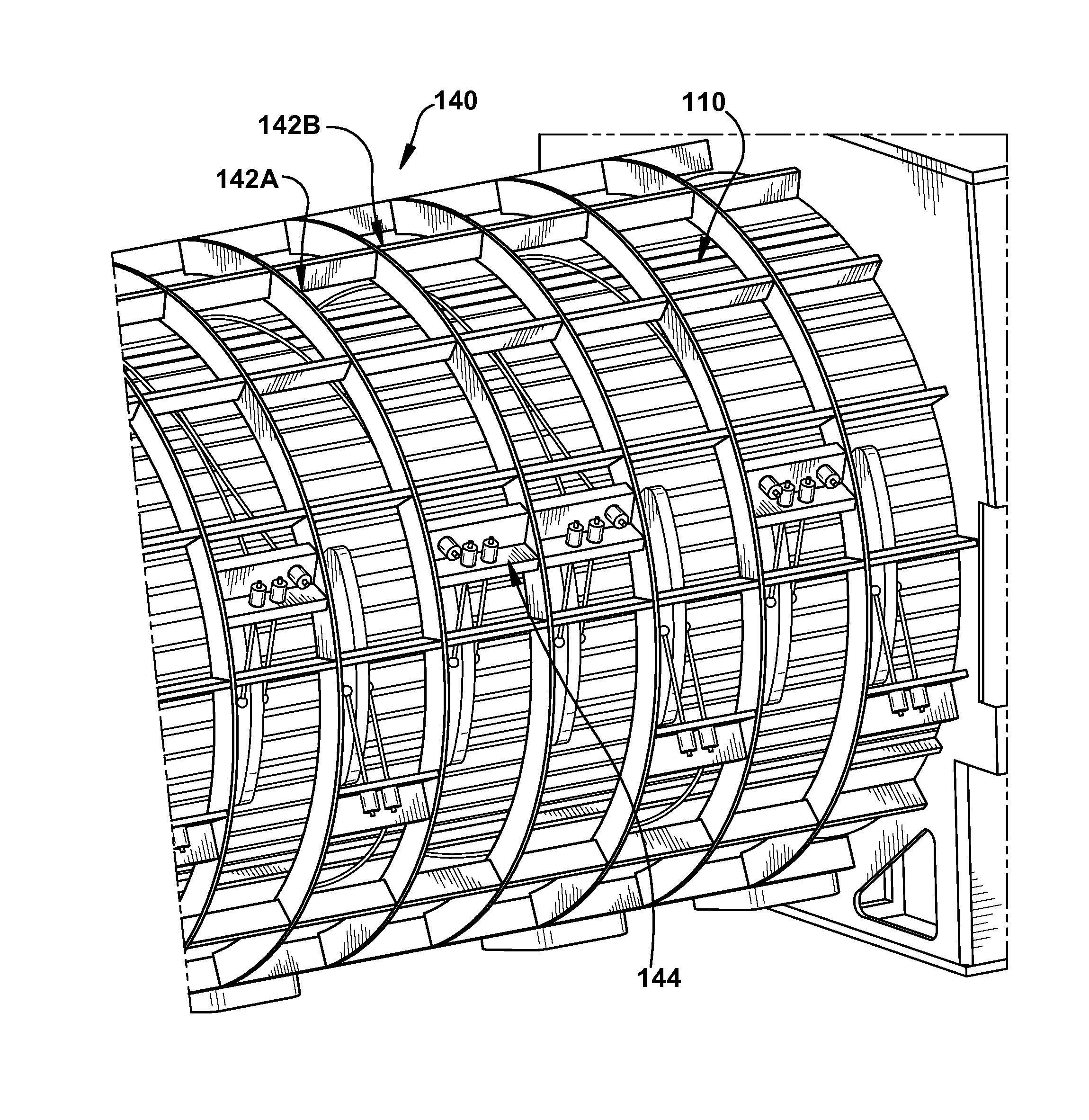
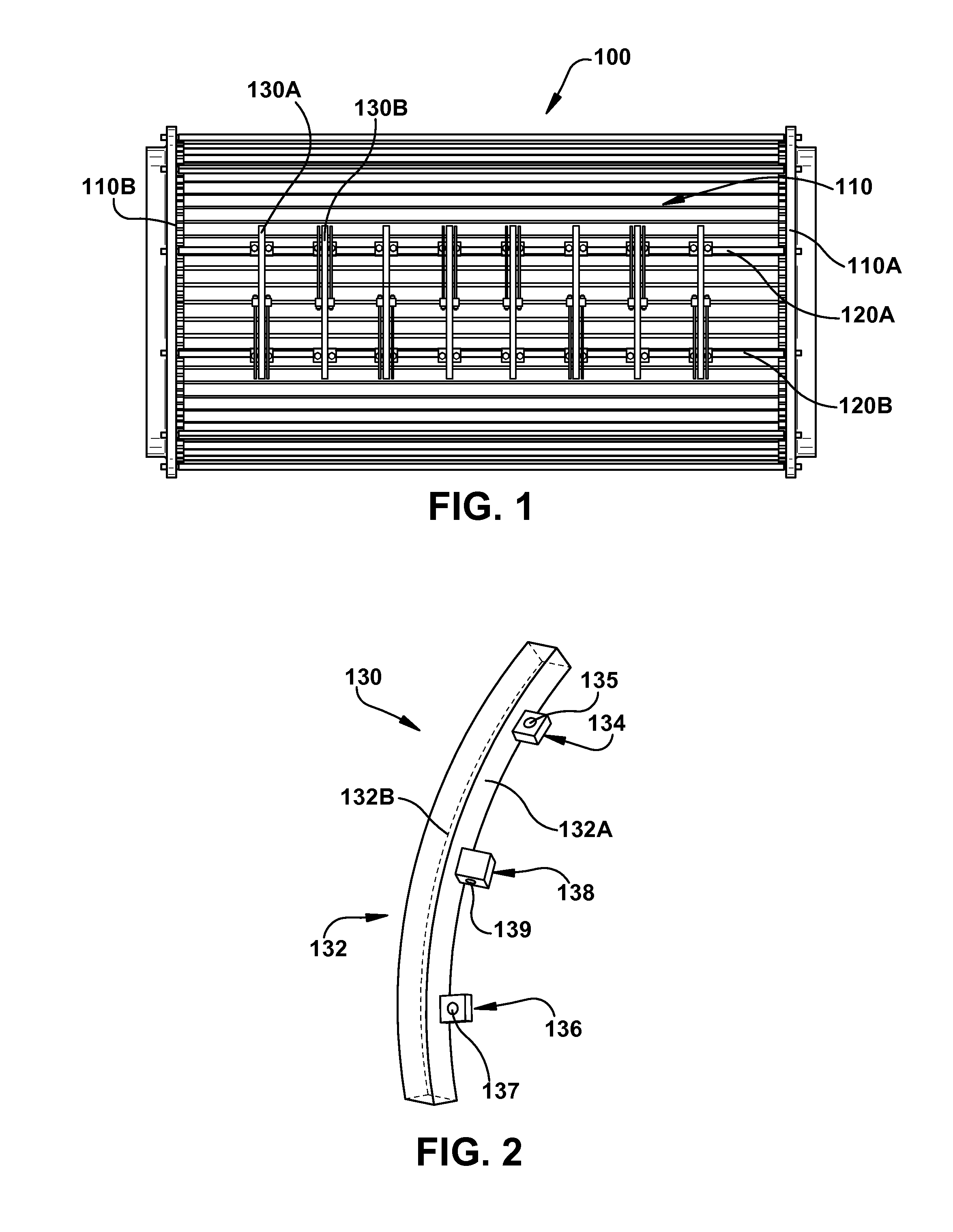
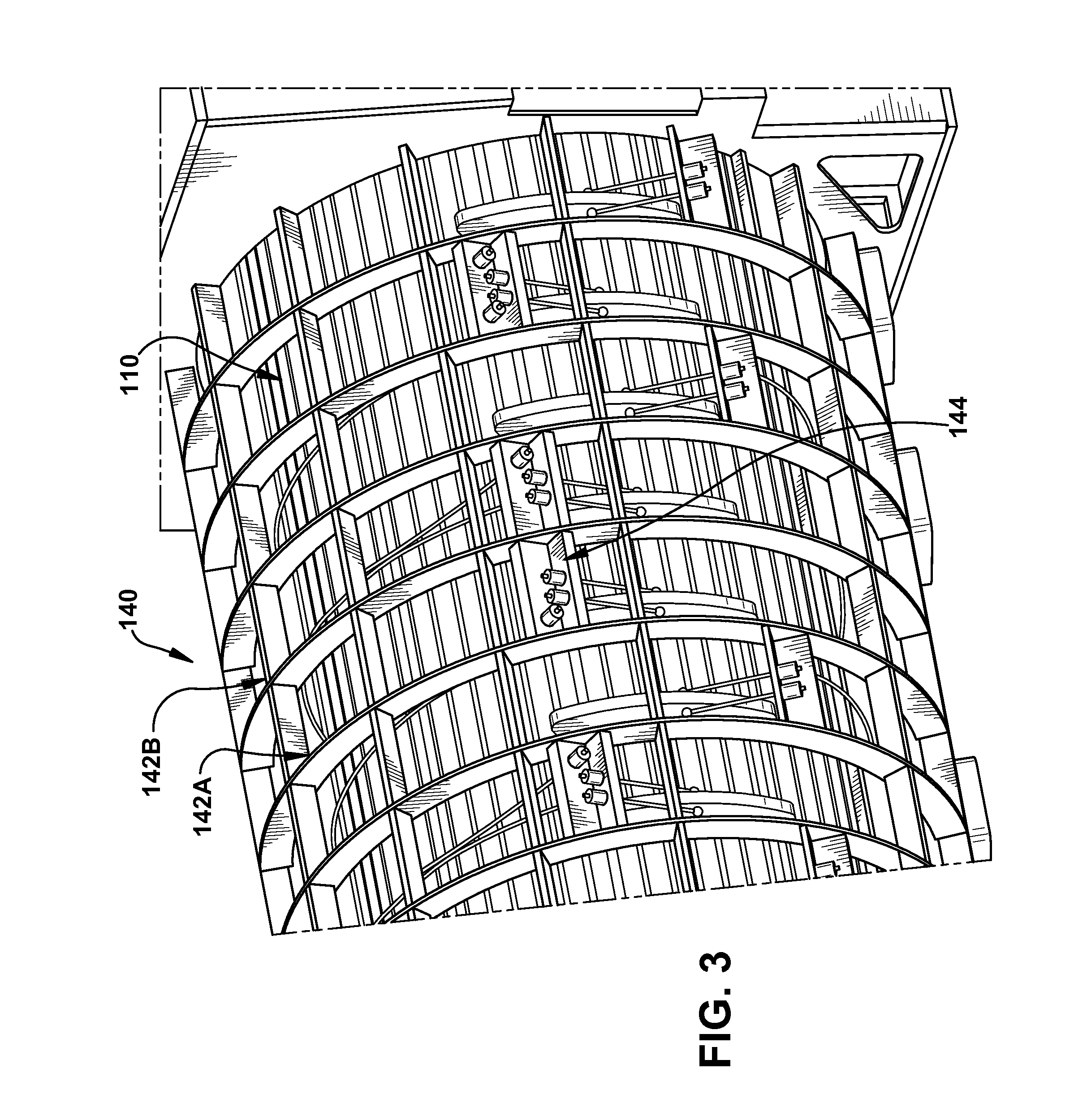
[0017]Turning now to the drawings, FIG. 1 shows a side view of a stator core 110 and support system 100 according to an embodiment of the invention. Support system 100 includes a plurality of key bar members 120A, 120B extending from a first end 110A to a second end 110B of stator core 110. Affixed to key bar members 120A and 120B are a plurality of support clamps 130A, 130B, etc.

[0018]FIG. 2 shows a detailed perspective view of a support clamp 130 according to an embodiment of the invention. Support clamp 130 includes an arcuate body 132 having a first surface 132A and a second surface 132B, and from which laterally extend a first affixation point 134, a second affixation point 136, and a securing point 138 therebetween. First and second affixation points are affixed to key bar members 120A and 120B (FIG. 1) using, for example, threaded members, welds, etc. One skilled in the art will recognize that any number of methods and techniques may be employed in affixing support clamp 130 ...


PUM


Abstract

Embodiments of the invention relate generally to turbo-generators and, more particularly, to suspension systems for turbo-generators and the attenuation of vibration in a stator core induced by an electromagnetic load. In one embodiment, the invention provides a support clamp comprising: an arcuate body; a first affixation point; a second affixation point; and a securing point between the first and second affixation points, wherein each of the first and second affixation points includes a radially-oriented opening extending from an inner surface to an outer surface and the securing point includes an area adjacent to an angled opening extending from a first surface to a second surface, each of the first and second surfaces lying substantially perpendicular to the inner and outer surfaces of the arcuate body.

Description

BACKGROUND[0001]The stator cores of turbo-generators, e.g., electric power generators, experience vibration due to the electromagnetic load of the machine. Left unattenuated, this vibration is capable of causing fatigue in the stator core and frame, which can shorten its useful life.[0002]Current attenuation systems include spring bars or similar devices affixed to the rigid stator frame structure surrounding the stator core. The components of such attenuation systems generally must be manufactured to small tolerances and are, therefore, relatively expensive to make, install, and service.[0003]Applicants have found that attenuation equivalent or superior to that achievable using known attenuation systems may be achieved through the use of flexible wire members to attach the stator core to the surrounding rigid frame structure. The angling of wire members at various locations and at various angles between the stator core and the frame structure provides a tunable isolation system. In...

Claims


Application Information

Patent Timeline
Patent Type & Authority Patents(United States)
IPC IPC(8): H02K1/18H02K5/24
CPCH02K1/185
Inventor YAMARTHI, DAVID RAJUKANAKAMEDALA, LAKSHMINARAYANATANAVDE, ANAND SHANKAR
Owner GENERAL ELECTRIC CO
Why Eureka
Try Eureka