Hot stamping machine

a stamping machine and hot stamping technology, applied in the direction of rotary presses, lamination apparatuses, decorative arts, etc., can solve the problems of impurities in stamping, and achieve the effect of preventing premature separation of transfer layers, fine resolution, and so small deflection

Active Publication Date: 2016-12-06
LEONHARD KURZ STIFTUNG & CO KG
View PDF19 Cites 0 Cited by
  • Summary
  • Abstract
  • Description
  • Claims
  • Application Information

AI Technical Summary

Benefits of technology

[0009]It may be provided that the support element is made of a material having a degree of hardness in the range of from 60° Shore A to 95° Shore A, preferably in the range of from 80° Shore A to 95° Shore A and / or a degree of hardness in the range of from 450 HV 10 (HV=Vickers hardness) to 520 HV 10, preferably in the range of from 465 HV 10 to 500 HV 10. Owing to this range of hardness, the support element can serve, particularly advantageously, as a mechanical counter-bearing for the substrate and the hot-stamping foil supported thereon, and prevent premature separation of the transfer layer and / or of the carrier layer from the substrate, in particular in the case of structures of the applied transfer layer that are of a particularly fine resolution.
[0010]Further, it may be provided that the support element is a rigid element, the maximum deflection of which, in the case of appropriate operational loading, is less than 10 μm, or is in the range of from approximately 1 μm to 10 μm. Since the degree of deflection is so slight, the support element can serve, particularly advantageously, as a mechanical counter-bearing for the substrate and the hot-stamping foil supported thereon, and prevent premature separation of the transfer layer and / or of the carrier layer from the substrate.
[0011]It may be provided, in an advantageous realization, that the support element is made of high-grade steel. A support element made of high-grade steel can impart, in particular, the aforementioned properties in respect of hard surface and slightness of deflection, and is particularly suitable as a mechanical counter-bearing for the substrate and the hot-stamping foil supported thereon. A further advantageous property of a support element made of high-grade steel is that, owing to the high thermal conductivity of high-grade steel, excess heat can be removed from the stamping gap, advantageously, by means of the belt. Particularly in the case of long stamping processes that run without interruption, it has been found that, in particular, the counter-pressure roller becomes ever hotter, despite additional cooling measures, and the stamping conditions in the stamping gap slowly deteriorate as a result. A support element made of high-grade steel can now additionally dissipate thermal energy out of the stamping gap, thereby allowing improved setting and control of the stamping conditions in the stamping gap.

Problems solved by technology

If the carrier film becomes separated too soon, impurities occur in the stamping, particularly in the case of fine and very fine structures.

Method used


Image

  • Hot stamping machine
  • Hot stamping machine
  • Hot stamping machine

Examples


Embodiment Construction

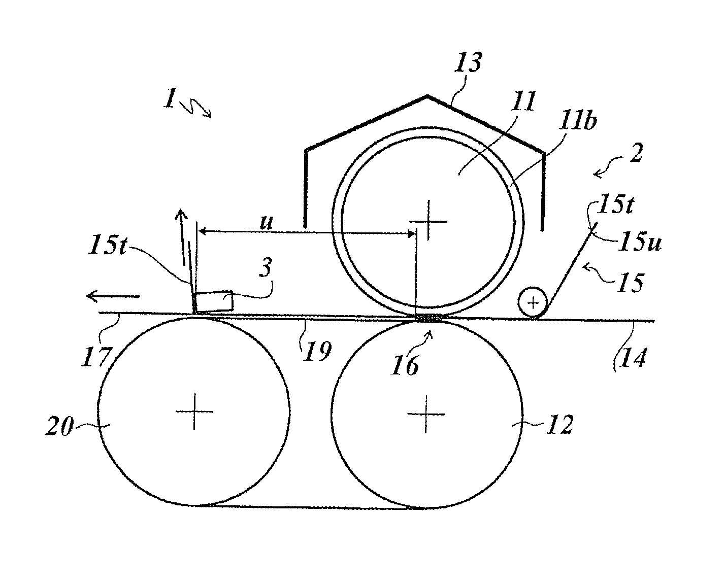
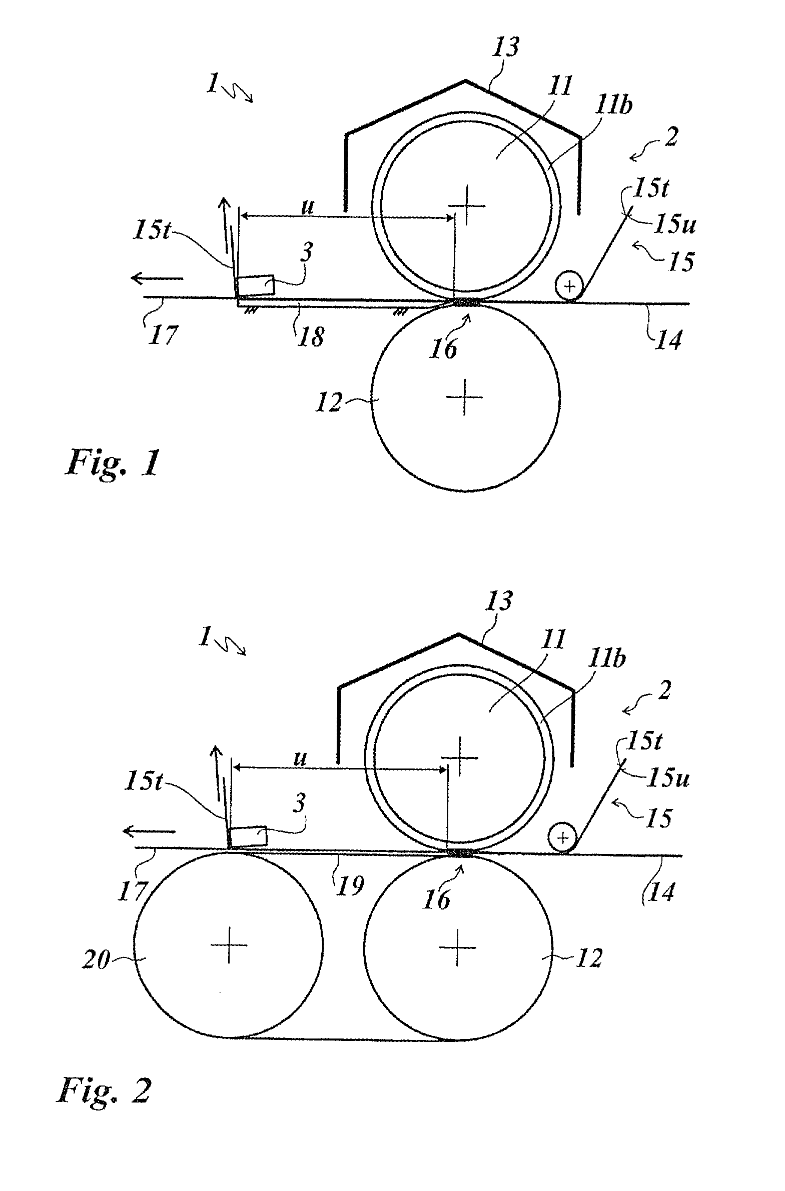
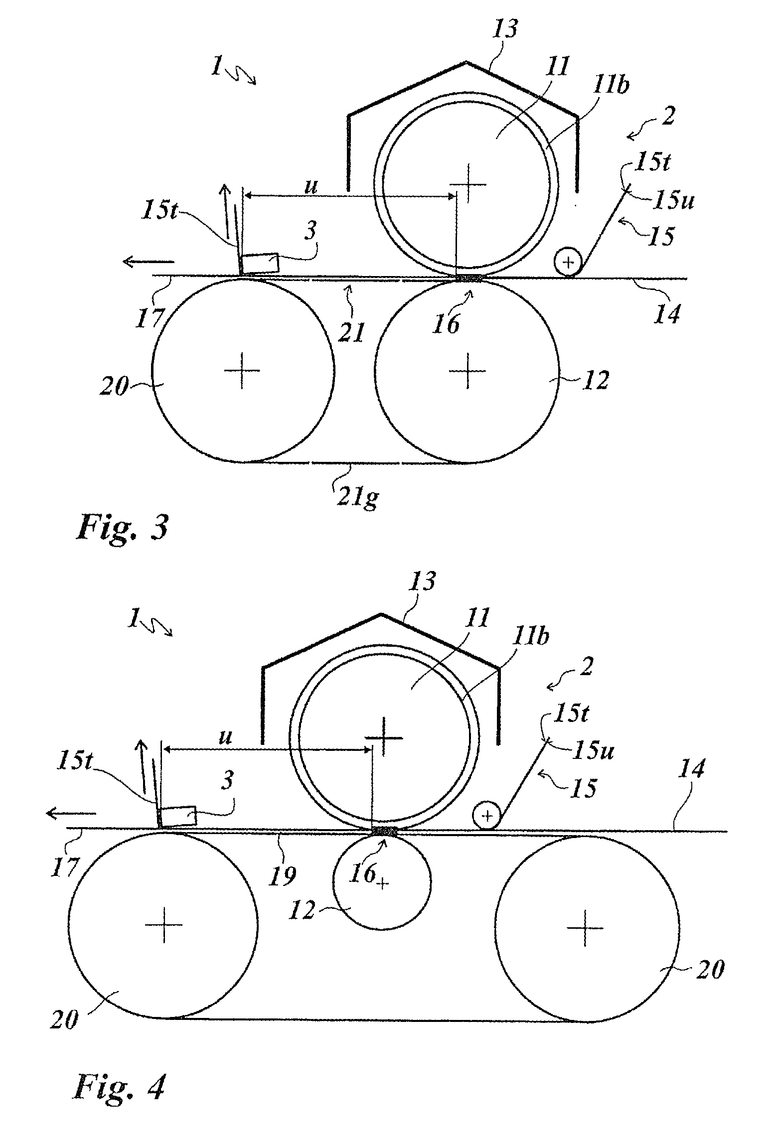
[0032]FIG. 1 shows a hot-stamping device 1 having a stamping device 2 and a separating device 3. The stamping device 2 comprises a stamping roller 11, a counter-pressure roller 12 and a heating apparatus 13.

[0033]On its external circumference, the stamping roller 11 has a coating 11b of an elastomer, having a thickness in the range of from 3 to 10 mm, preferably in the range of from 5 to 10 mm. The elastomer is preferably silicone rubber. In the embodiment example represented in FIG. 1, the silicone rubber has a hardness of 80° Shore A. The counter-pressure roller 12 is made of steel.

[0034]The heating apparatus 13 is disposed above the stamping roller 11 and, in the embodiment example represented in FIG. 1, is realized as infrared radiation heating controlled by means of a temperature controller.

[0035]Supplied upstream before the stamping device 2 are a substrate 14 to be stamped and a hot-stamping foil 15, which are joined together in a stamping gap 16 realized between the stamping...


PUM

PropertyMeasurementUnit
Vickers hardnessaaaaaaaaaa
thicknessaaaaaaaaaa

Abstract

A hot-stamping device (1) is described, having a stamping device (2) for transferring a transfer layer (15u) disposed on a carrier layer (15t) of a hot-stamping foil (15) on to a substrate (14). The hot-stamping device comprises a heatable stamping roller (11) and a counter-pressure roller (12), between which a stamping gap (16) is realized, and comprising a separating device (3), disposed downstream, for separating the carrier layer (15t) from the transfer layer (15u) transferred on to the substrate (14). A flat support element (18) is disposed under the stamped substrate (17), between the stamping gap (16) and the separating device (3), directly adjoining the stamping gap (16) or at a distance of <1 mm from the stamping gap (16) or overlapping the stamping gap (16).

Description

[0001]This application claims priority based on an International Application filed under the Patent Cooperation Treaty, PCT / EP2013 / 072087, filed on Oct. 22, 2013, and German Application No. DE 102012110149.3, filed on Oct. 24, 2012.BACKGROUND OF THE INVENTION[0002]The invention relates to a hot-stamping device according to the preamble of the subject-matter of claim 1.[0003]Hot-stamping devices are used to transfer a transfer layer disposed on a carrier layer of a hot-stamping foil on to a substrate by the action of temperature and pressure. For this, a heated stamping roller is provided, which acts in combination with a counter-pressure roller. By means of a separating apparatus, the carrier layer is drawn off downstream, after a stamping gap realized between the stamping roller and the counter-pressure roller, from the transfer layer that is transferred on to the substrate. If a profiled stamping roller is used, only regions of the transfer layer, in particular corresponding to th...

Claims


Application Information

Patent Timeline
Patent Type & Authority Patents(United States)
IPC IPC(8): B32B37/00B44B5/02B44B5/00B44C1/17B41F16/00
CPCB44B5/028B41F16/0026B41F16/0093B44B5/0047B44C1/17B44C1/1729
Inventor TRIEPEL, MICHAELBIEBER, RALPH
Owner LEONHARD KURZ STIFTUNG & CO KG
Why Eureka
Try Eureka