Supercharge Your Innovation With Domain-Expert AI Agents!

Cover and connection structure of housing and cover

a technology of connection structure and cover, which is applied in the direction of coupling/case, coupling device connection, electrical equipment, etc., can solve the problems of increasing the number of components and assembly cycles, poor workability, and defective conditions, so as to reduce the number of components and prevent the backlash of the cover. , the effect of reducing the cos

Active Publication Date: 2016-12-06
YAZAKI CORP
View PDF4 Cites 0 Cited by
  • Summary
  • Abstract
  • Description
  • Claims
  • Application Information

AI Technical Summary

Benefits of technology

The present invention aims to enhance workability by providing a cover and a connection structure between the housing and the cover. This can improve the overall performance and ease of use of the device.

Problems solved by technology

This unfortunately results in poor workability.
The hinge 113, which is prone to be distorted, disadvantageously causes a defective condition, such as breakage of the hinge 113, in addition to the above problems.
This unfortunately increases the number of components and the number of assembly cycles, resulting in an increase in cost.
This unfortunately results in inadequate engagement between the engaging arm 122 of the connector housing 101 and the engaged portion 201 of the counterpart connector 200.
Such a problem hinders a reliable fit between the connector 100 and the counterpart connector 200, and eventually loosens the fit between the connector 100 and the counterpart connector 200.

Method used


Image

  • Cover and connection structure of housing and cover
  • Cover and connection structure of housing and cover
  • Cover and connection structure of housing and cover

Examples


embodiment 1

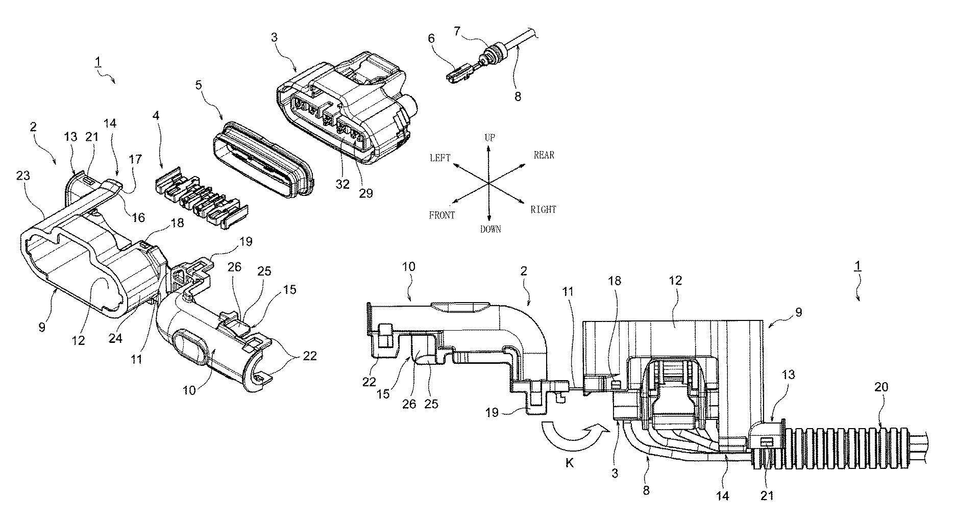
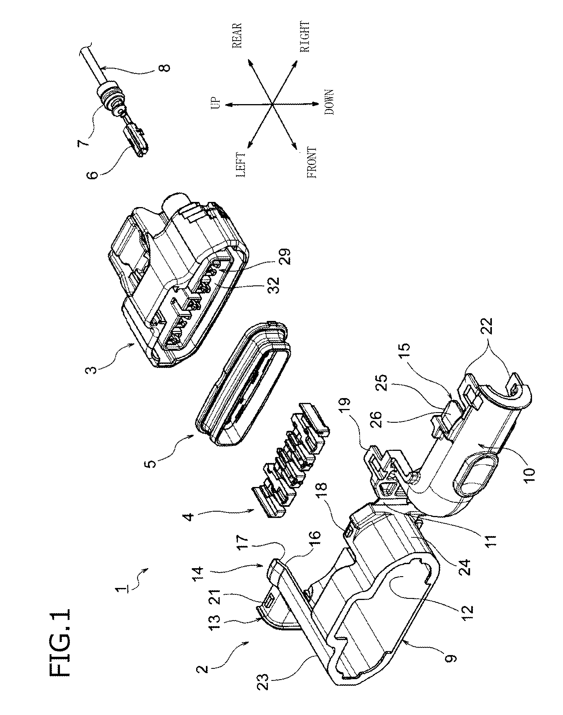
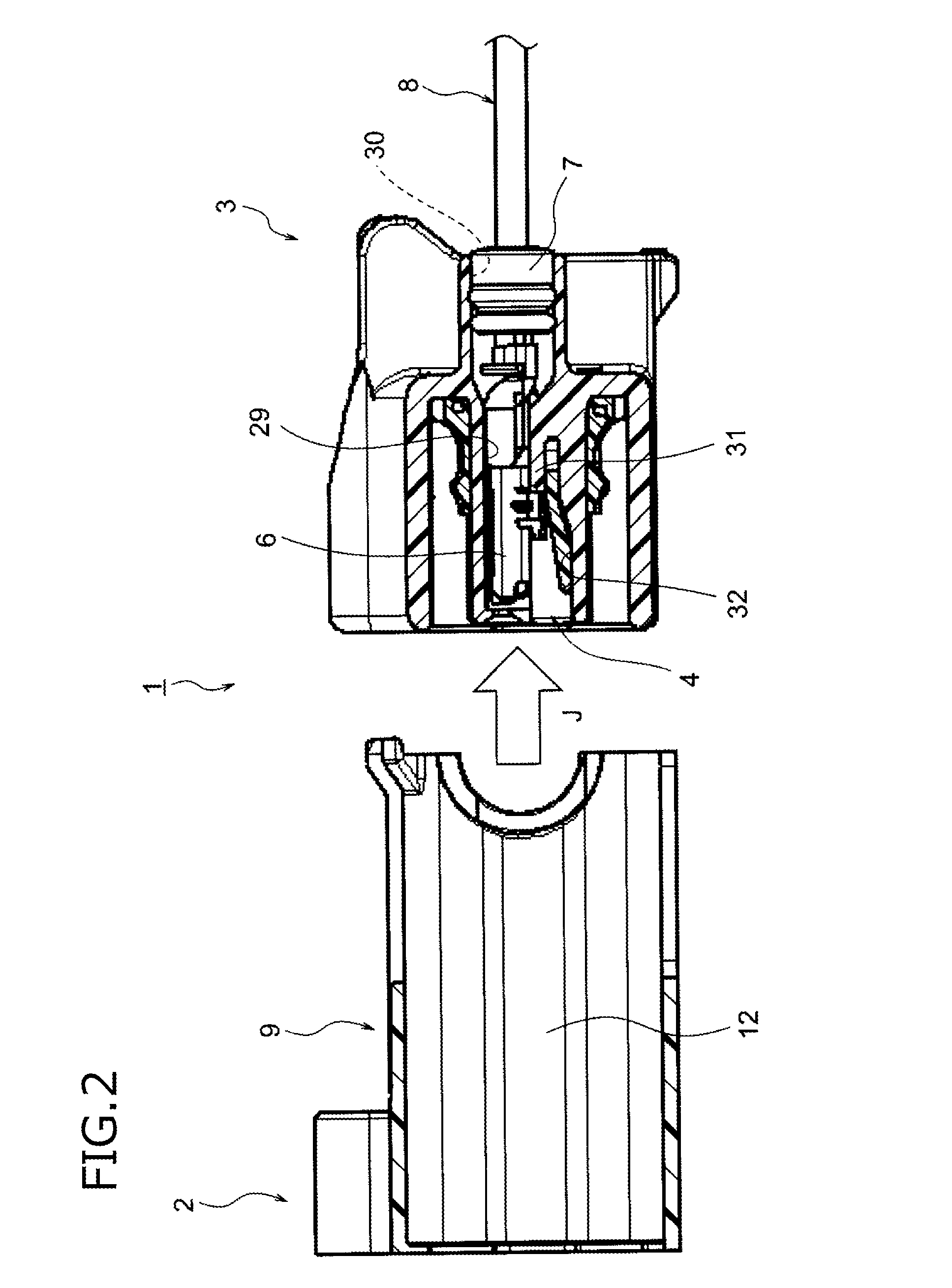
[0075]Embodiment 1 will now be described with reference to the drawings. FIG. 1 is an exploded perspective view of a connector according to Embodiment 1 of the present invention, including an inventive cover and serving as a connection structure. FIG. 2 is a cross-sectional view of the cover and a housing, illustrating how the cover and the housing are assembled to each other. FIG. 3 is a cross-sectional view of the cover and the housing assembled to each other. FIG. 4 is a plan view of the connector, illustrating how the body and lid of the cover are fitted to each other. FIG. 5 is a side view of the connector viewed from the lid of the cover, illustrating how the body and lid of the cover are fitted to each other. FIG. 6 is a cross-sectional view taken along the line L-L in FIG. 5. FIG. 7 is a cross-sectional view taken along the line M-M in FIG. 5. FIG. 8 is a cross-sectional view taken along the line L-L in FIG. 5, with the body and lid of the cover fitted to each other.

[0076]Th...

embodiment 2

[0129]The present invention provides, in addition to the cover according to Embodiment 1, a cover according to Embodiment 2 described below.

[0130]FIGS. 9A and 9B illustrate the cover according to Embodiment 2 of the present invention.

[0131]FIG. 9A is a perspective view of the cover according to Embodiment 2 of the present invention. FIG. 9B is an enlarged plan view of a hinge surrounded by the broken line N in FIG. 9A.

[0132]The arrows in FIG. 9A indicate, by way of example, forward, rearward, leftward, and rightward directions.

[0133]The cover 40 according to the present embodiment has a configuration and a structure similar to those of the cover 2 (see FIG. 1) described in Embodiment 1, except for the hinge 41 illustrated in FIG. 9A. Accordingly, the description of the components of the cover 40 according to the present embodiment other than the hinge 41 will be omitted.

[0134]The hinge 41 according to the present embodiment is configured so that a portion of the hinge 41 extending b...

embodiment 3

[0138]The present invention provides, in addition to the covers according to Embodiments 1 and 2, a cover according to Embodiment 3 described below.

[0139]FIGS. 10 to 13 illustrate the cover according to Embodiment 3 of the present invention.

[0140]FIG. 10 is a perspective view of the cover according to Embodiment 3 of the present invention. FIG. 11 is a cross-sectional view of the connector, illustrating how the body and lid of the cover are fitted to each other, with abutment portions yet to abut against the rubber stopper. FIG. 12 is a cross-sectional view of the connector, illustrating how the body and lid of the cover are fitted to each other, with the abutment portions abutting against the rubber stopper. FIG. 13 is a cross-sectional view of the connector, illustrating how the body and lid of the cover are fitted to each other, with the body and lid fitted to each other.

[0141]The arrows in FIGS. 10 to 12 indicate, by way of example, forward and rearward directions.

[0142]The cove...


PUM


Abstract

A cover includes a body attached to a housing containing a terminal connected to an electric wire, and that includes an electric wire leading portion, and a lid to be fitted to the body. The cover includes a guide receiving portion on an outer surface of a distal end of one of the lid and the body, and a guide portion on a distal end of the other. The guide receiving portion has an inclined surface inclined toward an inner surface of the guide receiving portion along a fitting direction. The guide portion guides a distal end of the guide receiving portion. The guide portion protrudes outward perpendicularly to the fitting direction. The guide portion has an inclined surface on an inner surface of the distal end of the other of the lid and the body.

Description

CROSS REFERENCE TO RELATED APPLICATION[0001]This application is based on Japanese Patent Application (No. 2014-240502) filed on Nov. 27, 2014, the contents of which are incorporated herein by reference. Also, all the references cited herein are incorporated as a whole.BACKGROUND OF THE INVENTION[0002]1. Technical Field[0003]The present invention relates to a cover including a body and a lid, and a connection structure of a housing and the cover.[0004]2. Background Art[0005]For example, a technique illustrated in FIG. 1 of JP-A-2013-8561 is conventionally used for a cover that protects electric wires placed into a connector housing and pulled out from the connector housing. A cover 10 illustrated in FIG. 1 of JP-A-2013-8561 is configured so that electric wires W placed into an electric wire pull-out portion of a connector housing 2 and pulled out from the connector housing 2 are led out through an electric wire container 14.[0006]To provide a cover configured so that electric wires p...

Claims


Application Information

Patent Timeline
Patent Type & Authority Patents(United States)
IPC IPC(8): H01R13/50H01R13/447
CPCH01R13/501H01R13/447
Inventor MASUI, YUKARISHIBATA, HISAYAHOMMA, HIDEKIWACHI, KOUHEINOGUCHI, MASAFUMIMIYAZAKI, HIROSHI
Owner YAZAKI CORP
Features
  • R&D
  • Intellectual Property
  • Life Sciences
  • Materials
  • Tech Scout
  • Unparalleled Data Quality
  • Higher Quality Content
  • 60% Fewer Hallucinations
Learn More