Earphone with stand-alone high-frequency driver
a driver and earphone technology, applied in the field of earphones, can solve the problems of affecting the production process, affecting the quality of earphones, and working less ideal in the high frequency range, so as to reduce manufacturing costs, avoid delay in product delivery, and shorten the production time of modified earphones
- Summary
- Abstract
- Description
- Claims
- Application Information
AI Technical Summary
Benefits of technology
Problems solved by technology
Method used
Image

Examples
first embodiment
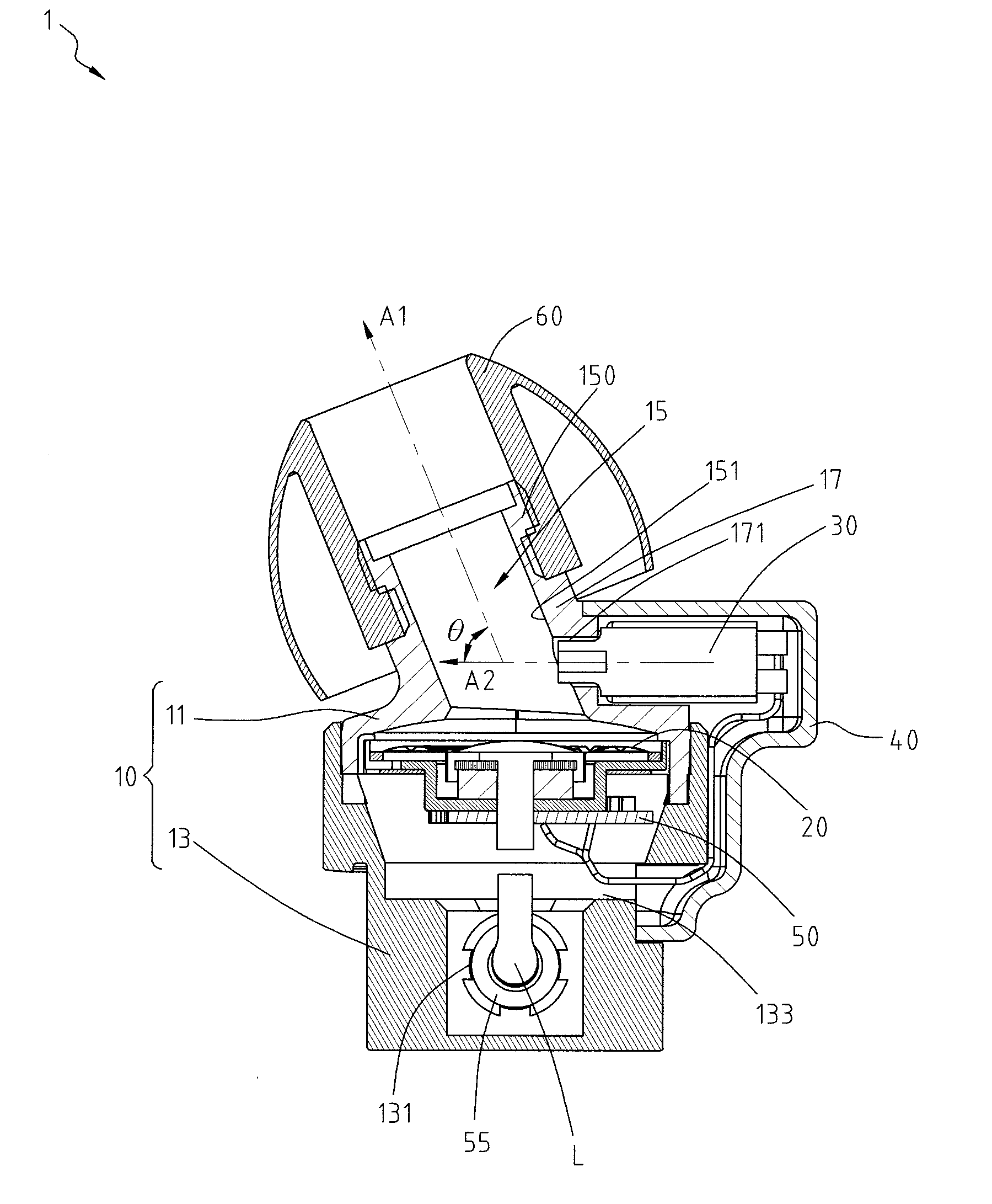
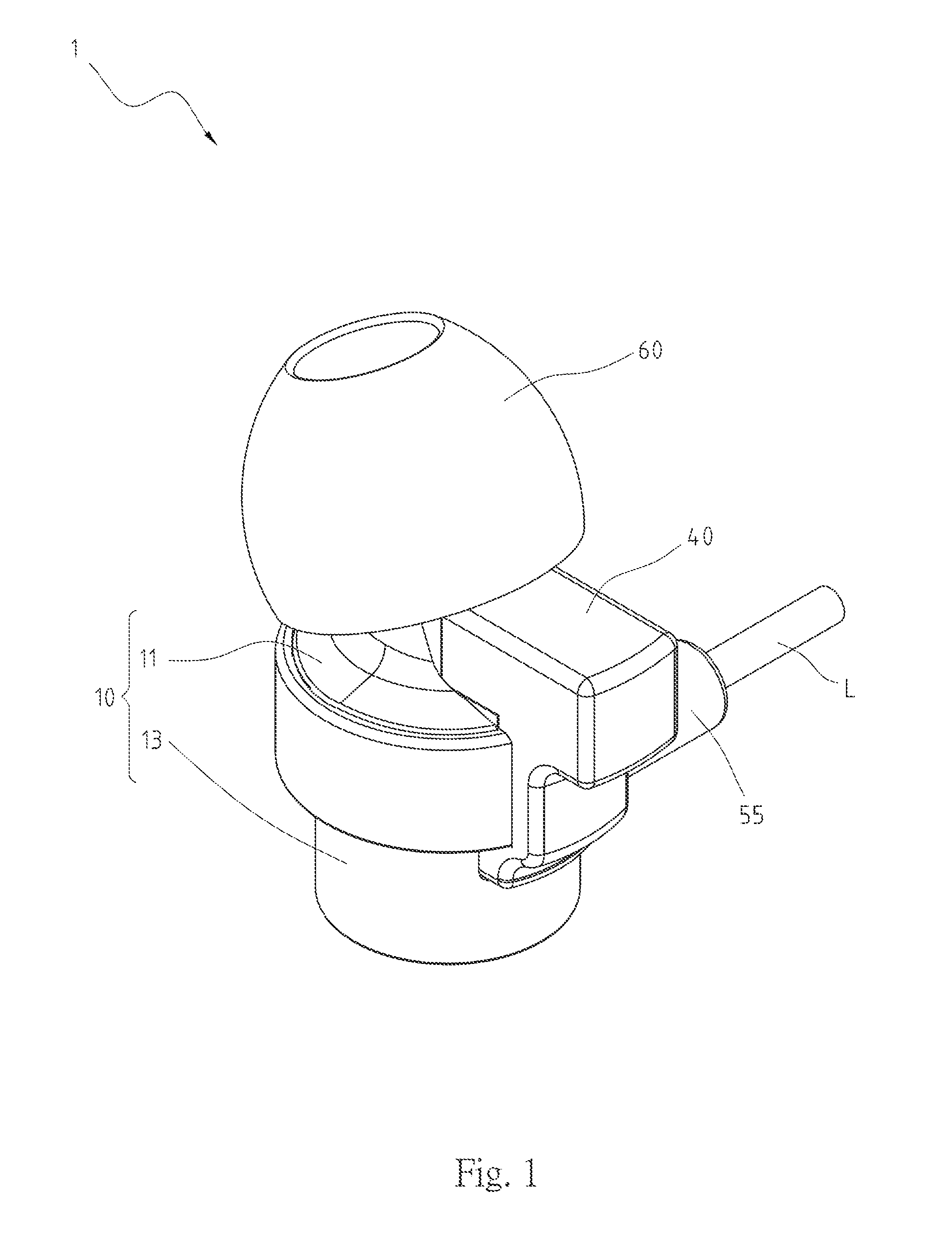
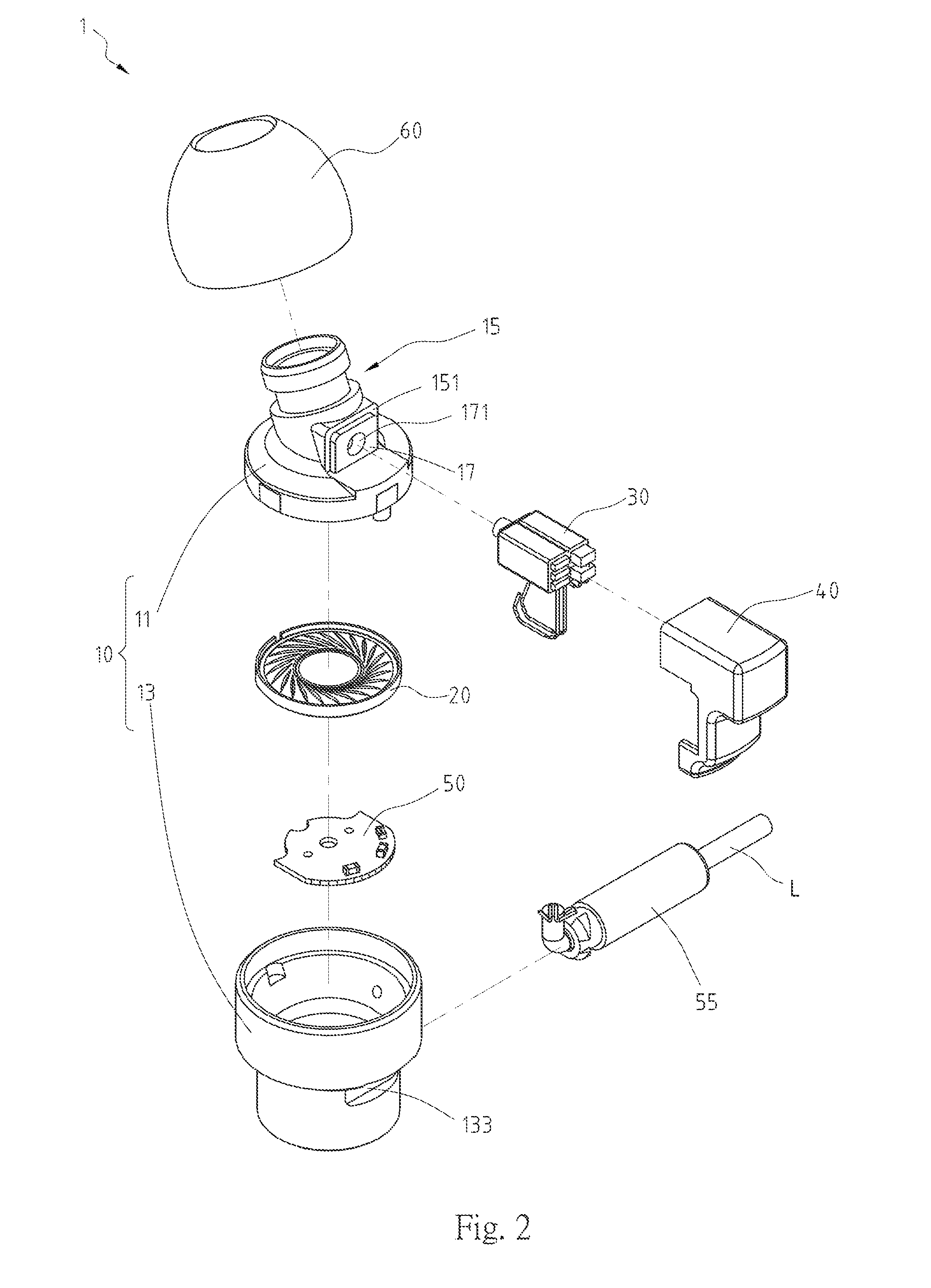
[0019]Please refer to FIGS. 1-3, which show a perspective view, an exploded view, and a cross-sectional view, respectively, of an earphone with stand-alone high frequency driver for the instant disclosure. As depicted in FIGS. 1-3, an earphone 1 comprises a casing 10, a low-frequency driver 20, a high-frequency driver 30, and a protecting cover 40. The casing 10 includes a front shell 11 and a rear shell 13 assembled to each other. The front shell 11 is formed with a sound-guiding passage 15 and a separating wall 17. The FIG. 3 illustrates the sound-guiding passage 15 is defined inside a tubular structure 150. The separating wall 17 is formed on a side surface 151 defined by the sound-guiding passage 15. A sound port 171 is further formed on the separating wall 17 and in acoustic communication with the sound-guiding passage 15. The rear shell 13 is formed with an access opening 131 and a via hole 133.
[0020]The low-frequency driver 20 is disposed in between the front and rear shells ...
second embodiment
[0023]Turning to FIGS. 4-6, which are a perspective, an exploded, and a cross-section view, respectively, of an earphone 2 with stand-alone high-frequency driver for the instant disclosure. As shown in FIGS. 4-6, the earphone 2 comprises the casing 10, low-frequency driver 20, high-frequency driver 30, and protecting cover 40 that corresponds to the features provided in the previous embodiment. The major differences being the shape of the casing 10, the manner in which high-frequency driver 30 is disposed, and the shape of the protecting cover 40.
[0024]For the second embodiment, the casing 10 includes a front shell 12 and the rear shell 13. In addition, since the connecting relationships between the rear shell 13, the low-frequency driver 20, and the circuit board 50 have already been described in the first embodiment, no further discussion is necessary. Only the differences between the two embodiments will be discussed in greater detail below.
[0025]The front shell 12 has a sound-gu...
PUM
 Abstract
Description
Claims
Application Information
 - R&D
- Intellectual Property
- Life Sciences
- Materials
- Tech Scout
- Unparalleled Data Quality
- Higher Quality Content
- 60% Fewer Hallucinations
Browse by: Latest US Patents, China's latest patents, Technical Efficacy Thesaurus, Application Domain, Technology Topic, Popular Technical Reports.
© 2025 PatSnap. All rights reserved.Legal|Privacy policy|Modern Slavery Act Transparency Statement|Sitemap|About US| Contact US: help@patsnap.com