Tube for pouring liquid metal, assembly of a tube and a metal frame and metal frame

a technology for liquid metal and tubes, applied in the direction of machine supports, household objects, applications, etc., can solve the problems of affecting the safety of operators, and achieve the effects of limiting splashing, reducing risk, and reducing the risk of operators

Active Publication Date: 2016-12-13
VESUVIUS GRP SA
View PDF16 Cites 0 Cited by
  • Summary
  • Abstract
  • Description
  • Claims
  • Application Information

AI Technical Summary

Benefits of technology

[0012]Thanks to the shape proposed hereinabove for the upstream part of the tube, it is possible to limit splashing or make the splashing less dangerous at the moment when the tube, which is being brought in or withdrawn during pouring, intersects the jet of liquid metal. In particular, thanks to the convex shape and narrow width of the upper end, the jet that intersects the tube is directed downwards on each side of the tube, which is less dangerous than when the end is flat and thick, or even concave, as in such cases the jet is sprayed towards the top of the tube and risks hitting an operator, especially at face level. Further, thanks to the relatively great length of the flared part and to the fact that it lies within a certain volume, the upstream part has surfaces capable of channelling the jet towards the downstream part of the tube. Specifically, thanks to the volume proposed hereinabove for the flared upstream part, those parts of the jet that ricochet off the internal surface of the upstream part will very probably then intersect some other part of this surface and then flow down inside the upstream part, thus preventing them from being thrown out of the tube. In particular, the frustoconical volume of angle alpha defines a first exclusion zone, in which there is no wall of the tube, guaranteeing that the upstream part is flared enough to be able to gather in a significant proportion of the jet leaving the container. Further, the second volume defined by the trapezium, the sides of which make the angle beta, guarantees firstly that the upstream part is not too flared, because if it were those parts of the jet that bounce off the inside of the upstream part would carry the risk of being thrown out of the tube, and secondly that the exterior surface of the upstream part has no projection that intersects the jet and that might cause the metal to ricochet towards the top of the tube.
[0019]According to an embodiment of the invention, the outer wall in the upstream part of the tube comprises a radius of curvature at the conical transition (i.e. the separation between the upper end of the tube and the remainder of the upstream part) so as to guide the liquid metal flow along the outer wall of the tube. In such a case, it is advantageous that the retaining device does not interfere with the liquid metal jet flowing along the wall. In a variant, the radius is eliminated. Instead the conical transition takes the shape o a sharp edge. The result is a flow separation from the tube outer wall and consequently, a deflection of the liquid metal jet from the tube outer wall away from the retaining device. Thereby, splashes due to liquid metal jet bouncing on the retaining device are reduced. In yet another variant designed to minimize contact of the liquid metal jet with the retaining device, the outer wall of the upstream part of the tube comprises a recess for hosting and protecting the retaining device.

Problems solved by technology

In particular, thanks to the convex shape and narrow width of the upper end, the jet that intersects the tube is directed downwards on each side of the tube, which is less dangerous than when the end is flat and thick, or even concave, as in such cases the jet is sprayed towards the top of the tube and risks hitting an operator, especially at face level.

Method used


Image

  • Tube for pouring liquid metal, assembly of a tube and a metal frame and metal frame
  • Tube for pouring liquid metal, assembly of a tube and a metal frame and metal frame
  • Tube for pouring liquid metal, assembly of a tube and a metal frame and metal frame

Examples


Embodiment Construction

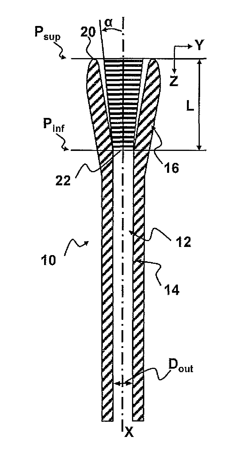
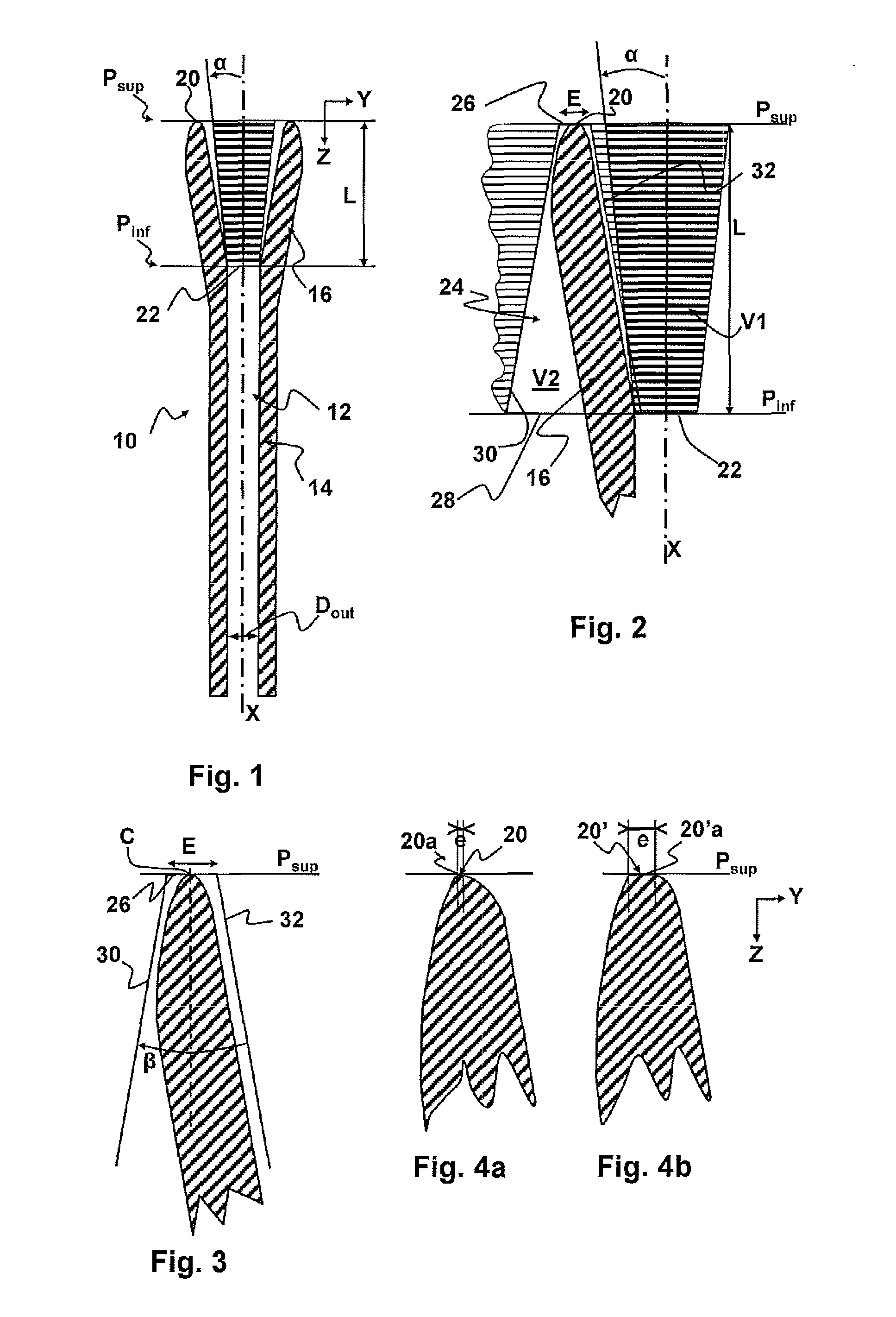
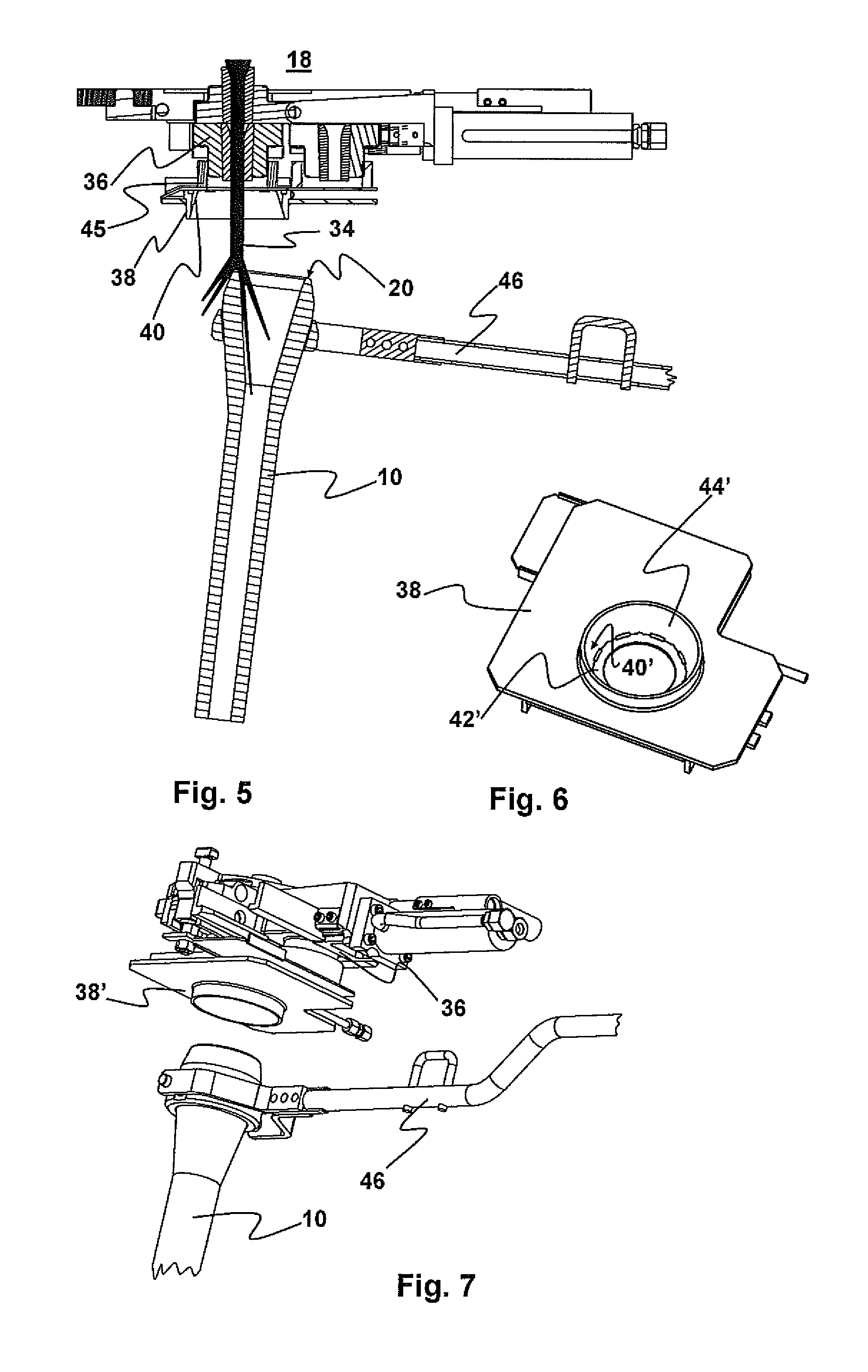
[0033]FIG. 1 depicts a tube 10 for pouring liquid metal from a metallurgical container 18 part of which is visible in FIG. 5. In this example, the container 18 is a tundish bath and the tube 10 is a shrouding tube for transferring the metal from the tundish 18 to a continuous casting mould (for example a billet mould; not depicted in the figures).

[0034]The tube 10 delimits a pouring channel 12, having a pouring axis X that coincides with the vertical direction Z when the tube is in the pouring position, against the container 18. The tube 10 comprises a downstream part 14, positioned at the end from which the liquid metal emerges, and an upstream part 16 positioned at the end from which the liquid metal enters the tube, at the container 18 end.

[0035]The downstream part 14 is cylindrical, its interior surface and its exterior surface each having as their directrix curve a circle the centre of which is on the pouring axis and having as their directrix straight line the pouring axis X. ...


PUM

PropertyMeasurementUnit
angleaaaaaaaaaa
angleaaaaaaaaaa
angle betaaaaaaaaaaa

Abstract

A tube for pouring liquid metal has a pouring channel with a pouring axis. The tube has a downstream part with a pouring channel with an outlet diameter, and a flared upstream part with a length known as the threshold distance. The threshold distance is greater than four times the outlet diameter. The upstream part is flared and configured so that its upper end has a convex overall shape in the axial direction. The upstream part is included within a first volume corresponding to the complementary part of an axisymmetric frustoconical volume having as its axis the pouring axis. The generatrix of the volume forms an angle greater than 5 degrees with the pouring axis. The upstream part is included within a second volume, delimited by a surface of revolution generated by an isosceles trapezium revolving about the pouring axis.

Description

BACKGROUND OF THE INVENTION[0001](1) Field of the Invention[0002]The present invention relates to the technical field of the continuous casting of liquid metal. It relates in particular to a tube for pouring liquid metal from a metallurgical container.[0003](2) Description of Related Art[0004]The prior art already discloses an installation for casting liquid metal, notably liquid steel, in which installation metal is transferred from a first metallurgical container to a second container. For example, the metal is transferred from a casting ladle to a tundish, or even from a tundish to casting moulds. To transfer liquid between the two containers use is generally made of a tube, such as a pouring tube, which is kept pressed against the first container, for example against a flow control valve positioned in the bottom of this container.[0005]In general, when the casting tube is brought against the container, pouring is halted. However, sometimes the tube is brought in or withdrawn whi...

Claims


Application Information

Patent Timeline
Patent Type & Authority Patents(United States)
IPC IPC(8): B22D41/50B22D41/56
CPCB22D41/502B22D41/56B22D41/50
Inventor DELSINE, DAMIENCOLLURA, MARIANO
Owner VESUVIUS GRP SA
Why Eureka
Try Eureka