Power transmission system of hybrid electric vehicle

a technology of hybrid electric vehicles and transmission systems, applied in vehicle sub-unit features, transportation and packaging, gearing, etc., can solve the problems of low fuel efficiency, insufficient power performance, and inability to achieve additional torque increasing devices, etc., and achieve the effect of sufficient power performan

Active Publication Date: 2016-12-13
HYUNDAI MOTOR CO LTD
View PDF8 Cites 2 Cited by
  • Summary
  • Abstract
  • Description
  • Claims
  • Application Information

AI Technical Summary

Benefits of technology

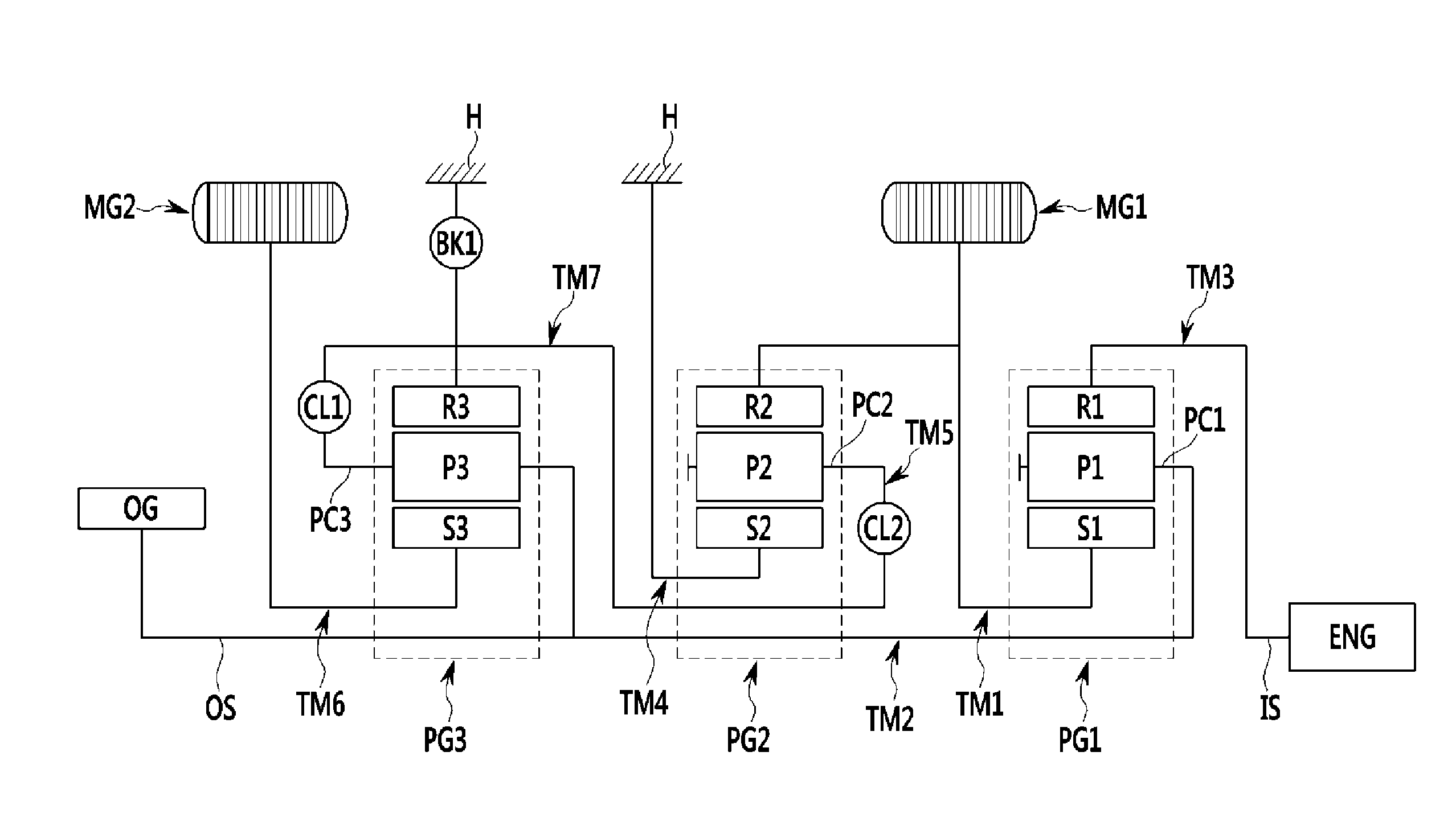
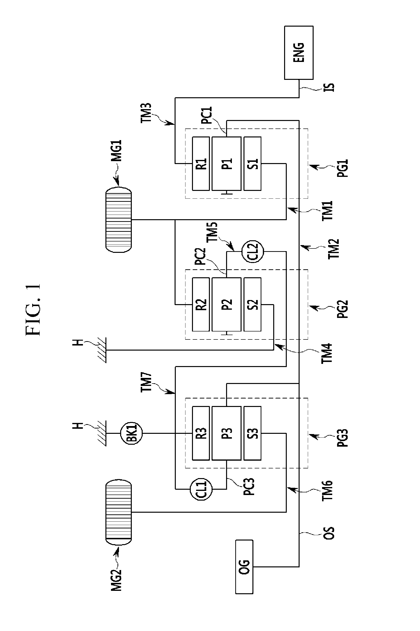
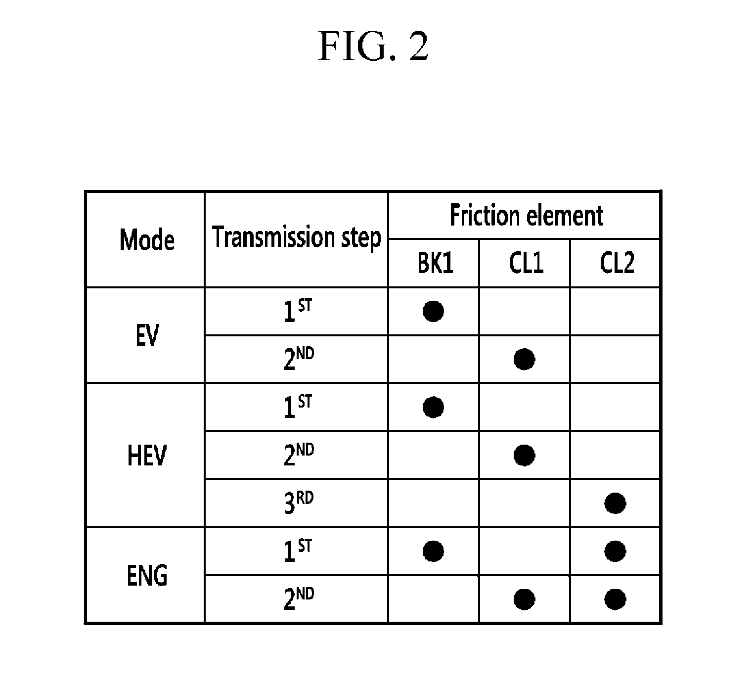
[0019]Various aspects of the present invention are directed to providing a power transmission system of a hybrid electric vehicle that can suppress conversion to an Engine (ENG) mode by providing sufficient power performance at the time of wide open throttle (WOT) launching and maximally use power of an engine at the time of conversion to a first Hybrid-Electric Vehicle (HEV) mode and a third HEV mode.
[0020]The present invention has also been made in an effort to provide a power transmission system of a hybrid electric vehicle that decreases an electric load by increasing a weight of a mechanical power transmission path to allow large engine power to be used, substitutes an ENG mode at the time of launching to decrease the number of mode conversion times, and minimizes a change in RPM of all rotating elements at the time of mode conversion.
[0021]The present invention has also been made in an effort to provide a power transmission system of a hybrid electric vehicle that can provide an ENG mode in which the vehicle can be driven without the electric load of a motor / generator for improving fuel efficiency at the time of high-speed driving.

Problems solved by technology

The single-mode scheme has an advantage that torque transmission mechanisms such as a clutch and a brake for transmission control are not required, but disadvantages that when the vehicle travels at a high speed, efficiency deteriorates, and as a result, the fuel efficiency is low and an additional torque increasing device is required to apply the single-mode scheme to large-sized vehicles.

Method used


Image

  • Power transmission system of hybrid electric vehicle
  • Power transmission system of hybrid electric vehicle
  • Power transmission system of hybrid electric vehicle

Examples


Embodiment Construction

[0046]Reference will now be made in detail to various embodiments of the present invention(s), examples of which are illustrated in the accompanying drawings and described below. While the invention(s) will be described in conjunction with exemplary embodiments, it will be understood that the present description is not intended to limit the invention(s) to those exemplary embodiments. On the contrary, the invention(s) is / are intended to cover not only the exemplary embodiments, but also various alternatives, modifications, equivalents and other embodiments, which may be included within the spirit and scope of the invention as defined by the appended claims.

[0047]Hereinafter, exemplary embodiments of the present invention will be described in detail with reference to the accompanying drawings.

[0048]However, parts which are not related with the description are omitted for clearly describing the exemplary embodiment of the present invention and like reference numerals refer to like or ...


PUM


Abstract

A power transmission system of a hybrid electric vehicle may include an input shaft, an output shaft, a first planetary gear set having three rotation elements, a second planetary gear set having three rotation elements, a third planetary gear set, a first shaft, a second shaft, a third shaft, a fourth shaft, a fifth shaft, a sixth shaft, and a seventh rotational shaft such that the power transmission system can suppress conversion to an Engine (ENG) mode by providing sufficient power performance at the time of wide open throttle (WOT) launching and maximally use power of an engine at the time of conversion to a first Hybrid-Electric Vehicle (HEV) mode and a third HEV mode.

Description

CROSS-REFERENCE TO RELATED APPLICATION[0001]The present application claims priority to and the benefit of Korean Patent Application No. 10-2014-0097364 filed on Jul. 30, 2014, the entire contents of which is incorporated herein for all purposes by this reference.BACKGROUND OF THE INVENTION[0002]Field of the Invention[0003]The present invention relates to a power transmission system of a hybrid electric vehicle, and more particularly, to a power transmission system of a hybrid electric vehicle that can suppress conversion to an Engine (ENG) mode by providing sufficient power performance at the time of wide open throttle (WOT) launching and maximally use power of an engine at the time of conversion to a first Hybrid-Electric Vehicle (HEV) mode and a third HEV mode.[0004]Description of Related Art[0005]Eco-friendly technology of a vehicle is a core technology influencing survival of a future vehicle industry and advanced vehicle makers devote all their might to developing eco-friendly ...

Claims


Application Information

Patent Timeline
Patent Type & Authority Patents(United States)
IPC IPC(8): B60K6/365B60K6/445B60K6/547F16H3/72F16H3/66
CPCB60K6/365B60K6/445B60K6/547F16H3/728F16H3/666F16H2200/201F16H2200/2038F16H2200/2097Y02T10/6239Y10S903/919Y02T10/62Y10S903/911B60K6/442B60Y2200/92B60Y2400/73F16H2200/0021F16H2200/0034F16H2200/0039
Inventor HWANG, DONGHWANLEE, CHANGWOOKPARK, JONGSOOLYANG, HORIMCHO, WONMIN
Owner HYUNDAI MOTOR CO LTD
Why Eureka
Try Eureka