
Method and apparatus for transmitting data in an automated control system

a technology of automated control system and data transmission, applied in the direction of transmission, programme control, total factory control, etc., can solve the problems of inability to determine short circuit or line break only through physical measurement methods, complex and expensive interbus concepts, and inability to implement at an acceptable speed using special protocol chips, etc., to achieve the effect of convenient and inexpensive manner

Active Publication Date: 2016-12-13
PILZ (COMPANY)
View PDF27 Cites 0 Cited by
  • Summary
  • Abstract
  • Description
  • Claims
  • Application Information

AI Technical Summary

Benefits of technology

[0008]Against this background, it is an object of the present invention to provide a method for allowing data communication of a distributed control system in an inexpensive and convenient manner.
[0009]It is also an object to provide a method for allowing simple and cost-effective data communication between a control unit and remote I / O units connecting various sensors and actuators to a central control unit.
[0010]It is yet another object to provide a method for data communication between a control unit and remote I / O units across a field bus having an efficient bus utilization with inexpensive hardware and low configuration complexity.

Problems solved by technology

It is a disadvantage of the Interbus that every station has to read out and write to a location within the data frame which is assigned to said station, and this can only be implemented at an acceptable speed using special protocol chips.
For applications in which only relatively small quantities of data are to be transmitted from and to a station, the Interbus concept is frequently too complex and too expensive.
In addition, the Ethernet telegrams require a relatively large protocol overhead and telegram overhead, and therefore the strengths of this known system are felt more in applications which require very powerful communication systems with relatively large information units.
These bus systems use a common bus line with the disadvantage that a short circuit or line break can only be determined by means of physical measuring methods, not from the data communication on the bus.
If the bus system also transmits safety-related data, such as for example information about the activation of an emergency-off button or a switch-off instruction for an actuator resulting therefrom, the address assignment is safety-related and therefore complex.

Method used


Image

  • Method and apparatus for transmitting data in an automated control system
  • Method and apparatus for transmitting data in an automated control system
  • Method and apparatus for transmitting data in an automated control system

Examples


Embodiment Construction

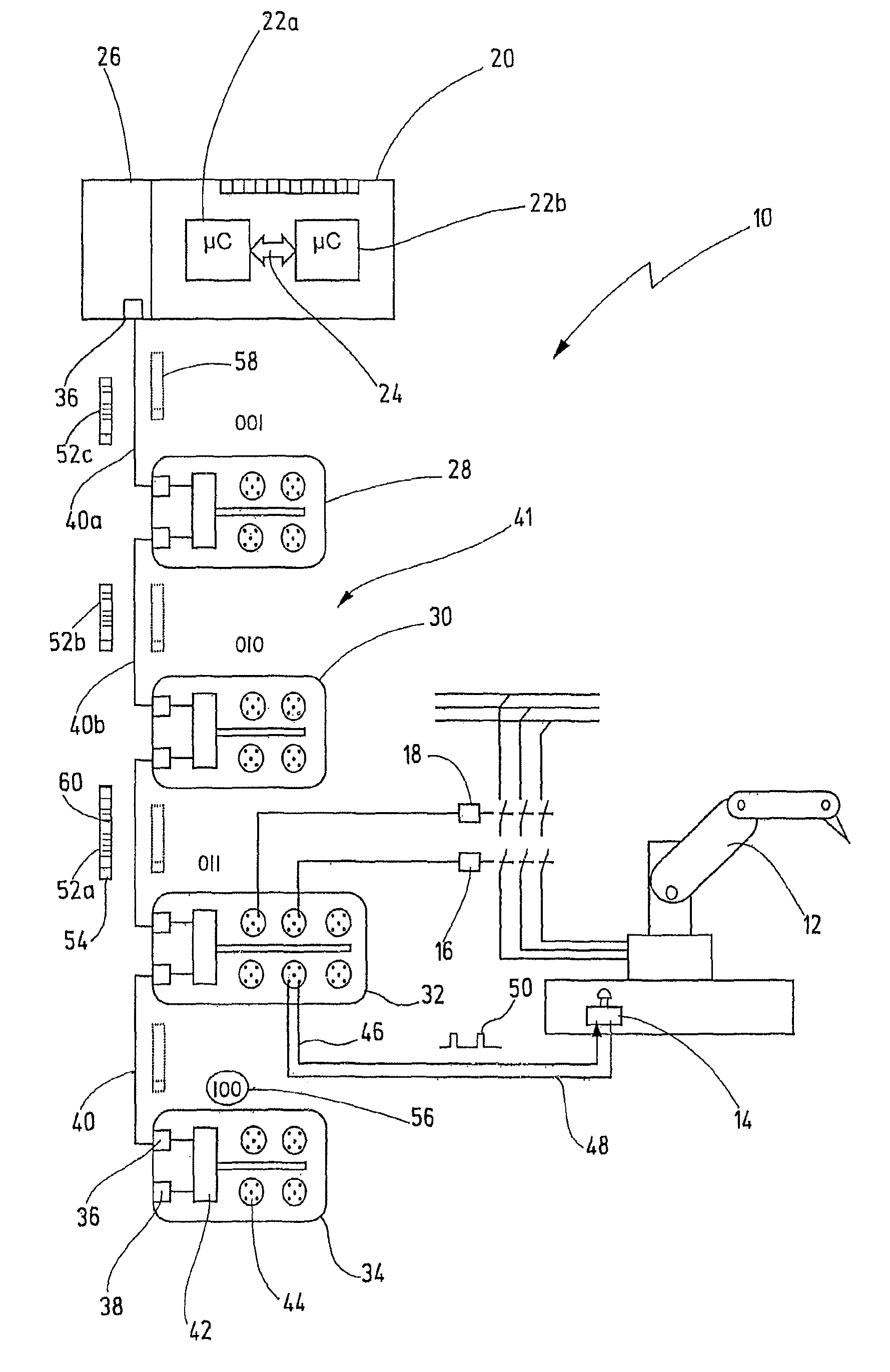
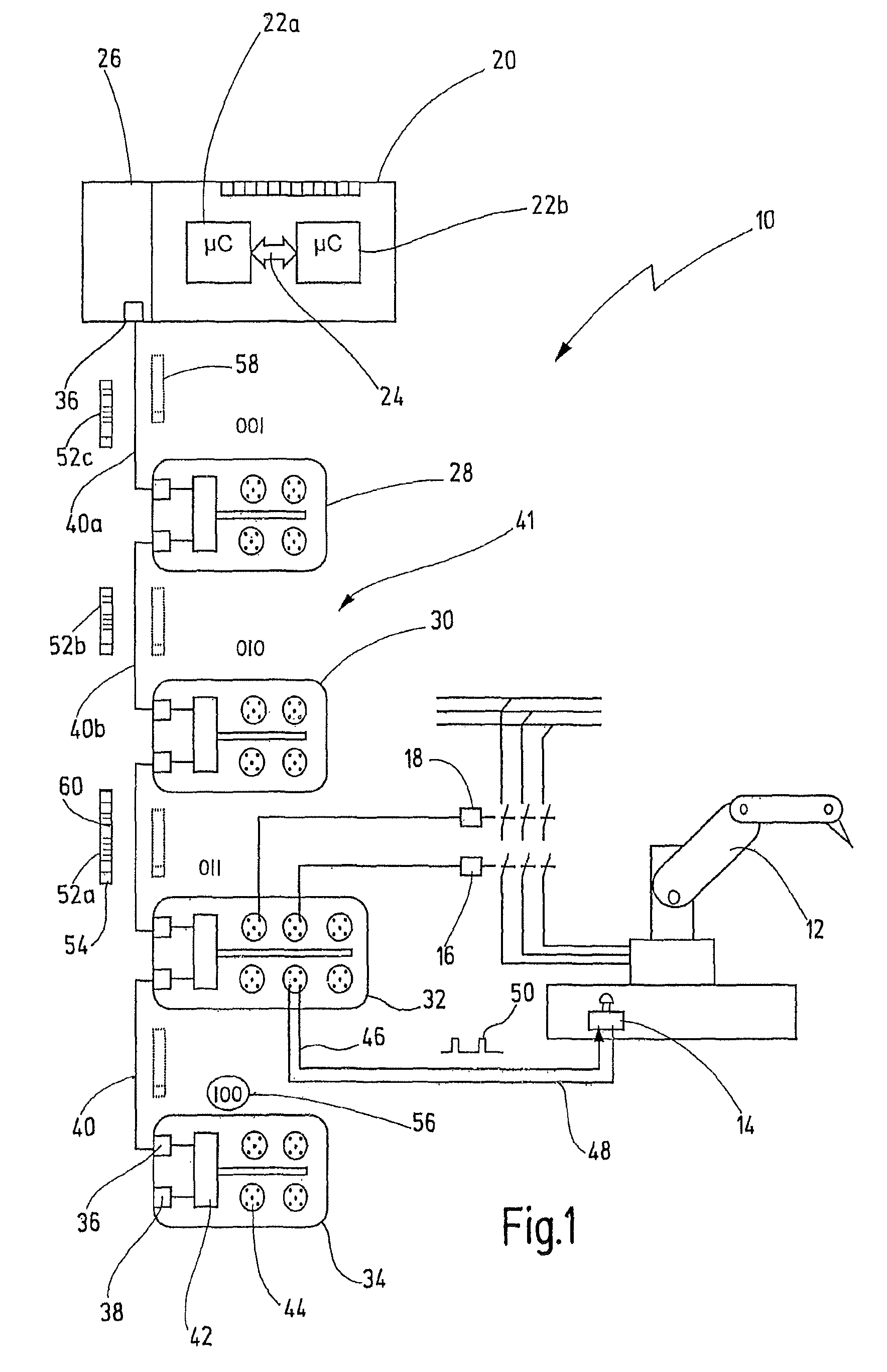
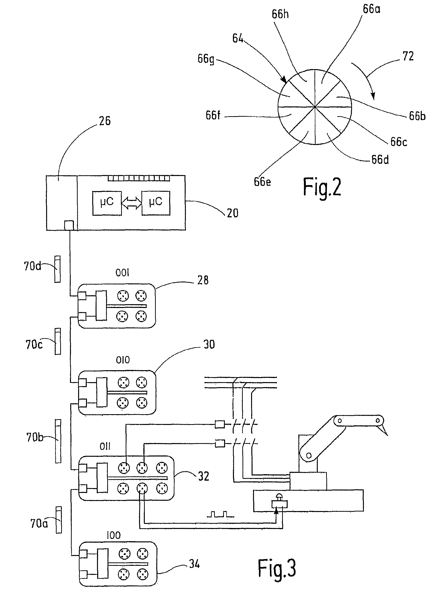
[0042]In FIG. 1, an exemplary embodiment of the new control system is denoted by the reference number 10 in its entirety. The control system 10 serves here to safeguard a robot 12 whose movements can pose a risk for persons owing to the speed and mass of the robot 12. Such robots are typically safeguarded using fixed protective fences and movable protective doors, light curtains and similar access protections as well as using emergency-off buttons. For the sake of simplicity, FIG. 1 merely illustrates one emergency-off button 14. A contact breaker is respectively illustrated by the reference numbers 16 and 18. The working contacts of the contact breakers 16, 18 are arranged in series with one another in the power supply path for the drives of the robot 12. When the emergency-off button 14 is activated, when a protective door opens or when a light curtain is traversed, the robot 12 must be shut down in a failsafe manner using the contact breakers 16, 18. “Failsafe” means in this cont...


PUM


Abstract

A control system has a plurality of spatially distributed stations. At least some of the stations have input connectors for connecting sensors or output connectors for connecting actuators. The stations are connected from station to station to form a series of stations. The series has a first station, at least one second station and a last station. The first station and every second station have a successor in the series. Every second station and the last station have a predecessor in the series. In order to transmit data in this control system, the first station generates a number of separate data telegrams which is equal to the number of second stations plus the last station. Each data telegram is addressed to precisely one of the stations. The first station sends the data telegrams on by one at defined time intervals to its successor, wherein the data telegrams are addressed in reverse order of the stations. Every second station receives a data telegram from its respective predecessor and sends the received data telegram to its respective successor in the manner of a bucket brigade until it receives a data telegram which is addressed itself. The second stations and the last station each generate an individual reply telegram which is directed to the first station, and send the individual reply telegrams to their respective predecessors in the manner of a bucket brigade.

Description

CROSS REFERENCES TO RELATED APPLICATIONS[0001]This application is a continuation of international patent application PCT / EP2009 / 008261 filed on Nov. 20, 2009 designating the U.S., which international patent application has been published in German language and claims priority from German patent application DE 10 2008 060 007.5 filed on Nov. 25, 2008. The entire contents of these priority applications are incorporated herein by reference.BACKGROUND OF THE INVENTION[0002]The present invention relates to a method for transmitting data in an automated control system having a plurality of spatially distributed stations which communicate via a communication medium, and to a corresponding control system and station. In particular, the invention relates to a method which allows a control unit to communicate with remote I / O station of an automated control system in a simple and inexpensive manner.[0003]The use of what is called field buses for data communication among a plurality of stations...

Claims


Application Information

Patent Timeline
Patent Type & Authority Patents(United States)
IPC IPC(8): H02J13/00G05B19/418H04L12/403
CPCG05B19/4186H04L12/403G05B2219/25213Y02P90/185G05B2219/21033G05B2219/25002Y02P90/02
Inventor SCHWENKEL, HANS
Owner PILZ (COMPANY)
Learn More