Electrical connector

Active Publication Date: 2016-12-20
CHENG UEI PRECISION IND CO LTD
View PDF14 Cites 31 Cited by
  • Summary
  • Abstract
  • Description
  • Claims
  • Application Information

AI Technical Summary

Benefits of technology

[0008]As described above, the lower connecting piece of each of the lower ground terminals contacts with the bottom surface of the middle shielding plate, and the upper connecting piece of each of the upper ground terminals contacts with the top surface of the middle shielding plate, electromagnetic interferences will be effectively eliminated between the lower terminals and the upper terminals to improve signal transmission qualities of the lower terminals and the upper terminals. In addition, the outer shell is mounted outside

Problems solved by technology

With the development of electronic industries, a conventional USB 2.0 electrical connector needs to be distinguished an obverse surface from a reverse surface to be inserted and a drawback of a lower transmission speed is gradually emerged.
But the above-mentioned structure will cause a series of problems, especially, electromagnetic interferences will be generated between the first terminals and the second terminals to affect signal transmission qualities of the

Method used


Image

  • Electrical connector
  • Electrical connector
  • Electrical connector

Examples


Example

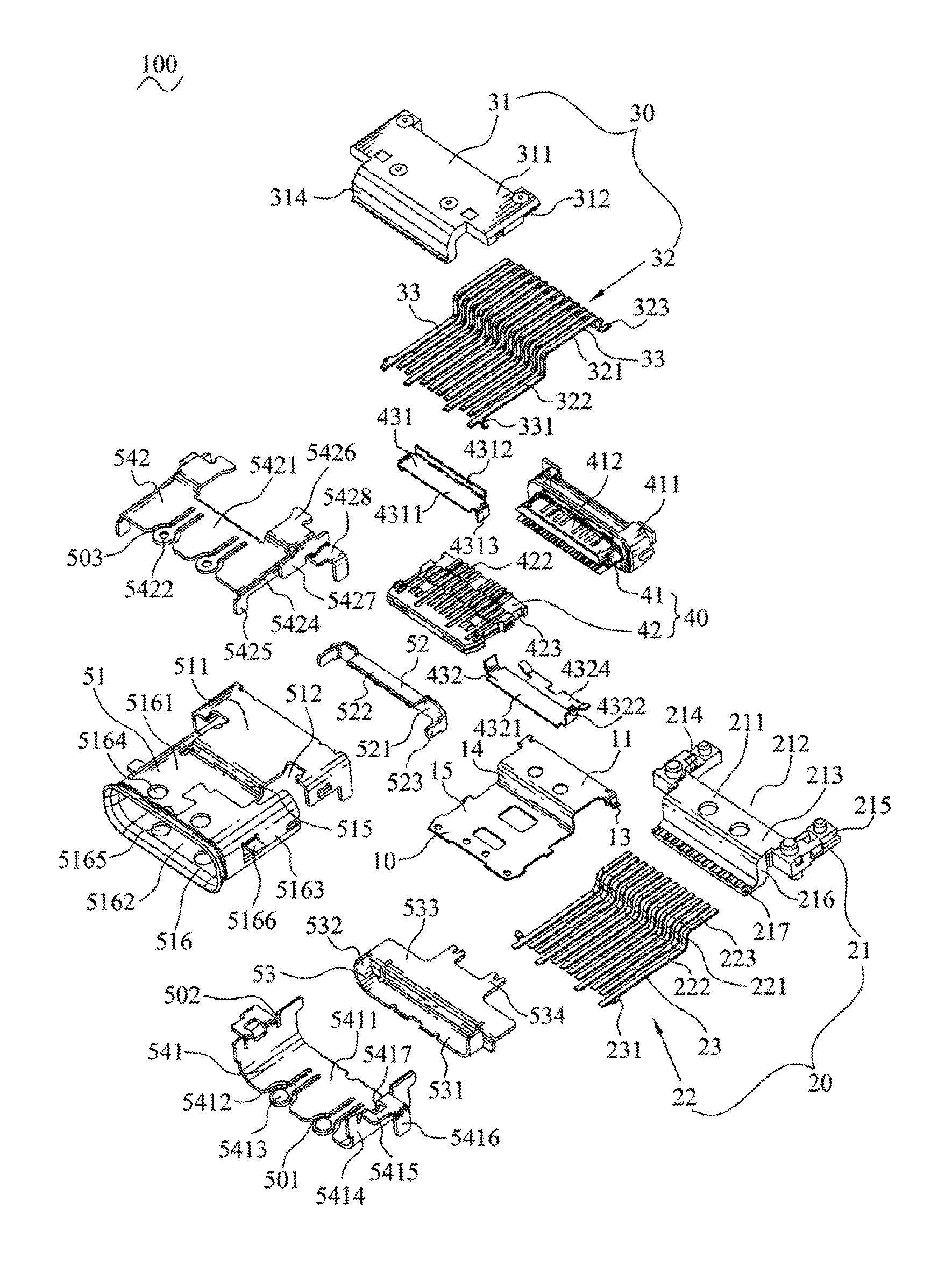
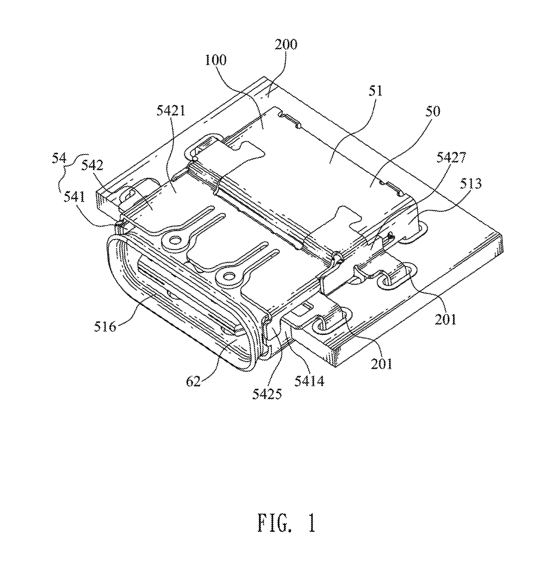
[0021]With reference to FIG. 1 and FIG. 3, an electrical connector 100 in accordance with the present invention is shown. The electrical connector 100 mounted to a circuit board 200, includes a middle shielding plate 10, a lower terminal module 20, an upper terminal module 30, an insulation module 40 and a shielding shell 50.

[0022]Referring to FIG. 3 and FIG. 4, the middle shielding plate 10 has a restricting plate 11, an abutting plate 12 bent downward from a rear end of the restricting plate 11, and a soldering arm 13 connected with the restricting plate 11. Rear ends of two opposite sides of the restricting plate 11 are bent downward and then are bent outward to form two soldering arms 13. A front end of the restricting plate 11 is bent downward to form a front plate 14. A bottom end of the front plate 14 is bent frontward and further extends frontward to form a tongue plate 15.

[0023]Referring to FIG. 3 and FIG. 5, the lower terminal module 20 includes a lower insulating housing ...


PUM


Abstract

An electrical connector includes a middle shielding plate, a lower terminal module, an upper terminal module mounted on a top surface of the middle shielding plate, an insulation module and a shielding shell. The middle shielding plate is mounted on the lower terminal module. The lower terminal module includes a plurality of lower terminals which include two lower ground terminals. A front end of an outer side of each of the lower ground terminals is connected with a lower connecting piece. The upper terminal module includes a plurality of upper terminals which include two upper ground terminals. A front end of an outer side of each of the upper ground terminals is connected with an upper connecting piece. The shielding shell is mounted outside the lower terminal module, the upper terminal module and the insulation module.

Description

BACKGROUND OF THE INVENTION[0001]1. Field of the Invention[0002]The present invention generally relates to a connector, and more particularly to an electrical connector capable of realizing a normal insertion and a reverse insertion.[0003]2. The Related Art[0004]With the development of electronic industries, a conventional USB 2.0 electrical connector needs to be distinguished an obverse surface from a reverse surface to be inserted and a drawback of a lower transmission speed is gradually emerged. The conventional USB 2.0 electrical connector includes an insulating housing and a plurality of first terminals. The insulating housing has a base portion and a tongue board protruded frontward from a front surface of the base portion. The first terminals are fastened to the insulating housing with front ends of the first terminals being exposed to a top surface of the tongue board. In order to realize a normal insertion and a reverse insertion of the USB 2.0 electrical connector, a plura...

Claims


Application Information

Patent Timeline
IPC IPC(8): H01R13/648H01R13/6581H01R13/6597H01R24/68H01R13/62
CPCH01R13/6581H01R13/62H01R24/68H01R13/6597H01R13/6582H01R24/60
Inventor SU, YU-HUNGWANG, CHIN-CHOU
Owner CHENG UEI PRECISION IND CO LTD
Why Eureka
Try Eureka