Header with center part and side parts adjustable relative to the center part

a technology of center part and side parts, applied in the field of multi-part headers, can solve the problems of unsusceptible support of two side parts, achieve the effect of reducing the leverage force acting on the feed channel and the frame of the combine harvester, achieving faster and easier, and absorbing high loads

Active Publication Date: 2016-12-27
CARL GERINGHOFF GMBH & CO KG
View PDF10 Cites 14 Cited by
  • Summary
  • Abstract
  • Description
  • Claims
  • Application Information

AI Technical Summary

Benefits of technology

[0008]According to one embodiment of the invention, the ball joint is arranged adjacent to the feed channel and in the area of the lower half of the feed channel, the ball joint is connected to the lateral frame and the attachment frame by means of a rigid guide arm, and a pivot movement of the lateral frame supported by the ball joint transverse to the travel direction is adjustable by means of actuation of a motorically adjustable guide arm which, with a first end, engages at a spacing to the ball joint at a point of attack provided on the lateral frame and, with a second end, is connected to the center part or the attachment frame. Due to the arrangement of the ball joint in the area of the lower half of the feed channel, the center of gravity of the total construction remains low and close to the ground, and the belt length of the belt conveyor transporting transversely to the travel direction is not changed upon pivoting about the axis of rotation which extends in the travel direction. By the arrangement adjacent to the feed channel, the latter can remain unchanged. Due to the rigid configuration of the connecting guide arms, defined positions and movement possibilities for the side parts relative to the fixed position of the respective ball joint result. The rigid guide arms can be designed to match exactly the bearing loads that are to be absorbed by them. Based on the spacing between the ball joint and the point of attack, geometries for adjusting strokes result by means of which the side parts can be pivoted from one extreme position into another extreme position and into any position in between. The motorically adjustable guide arm enables by means of an appropriate configuration an automation of the continuous ground adjustment of the pivot position as well as remote operation from the driver's cabin. With the motorically adjustable guide arm, a lateral frame can be lifted or lowered into a pivot position in which the cutter bar that is attached to the front side of the lateral frame is aligned at least approximately parallel to the ground contour across the width of the lateral frame, and the grain to be harvested with the header can be cut close to the ground without crop losses caused by the crop being cut too high and can be transported into the combine harvester. With an appropriate power of the servomotor, an adjusting speed is possible with which the pivot position of the lateral frame can be continuously adapted to changes of the ground contour upon forward travel of the combine harvester across a field to be harvested without the lateral frame colliding with the ground and thereby damaging the header.
[0009]According to one embodiment of the invention, the motorically adjustable guide arm is designed as a length-adjustable hydraulic cylinder. A hydraulic cylinder as a servomotor can be integrated easily into the control and governing system of an agricultural machine. By means of a hydraulic cylinder, high adjusting forces can be transmitted, accompanied by precise adjustability of the pivot position of the lateral frame.
[0010]According to one embodiment of the invention, the lateral frame is supported additionally by a single-acting or double-acting force store against the center part or the attachment frame. As a force store, mechanical springs, but also alternatively or in combination, a pneumatic or hydraulic buffering action by means of pressure control valves is conceivable. The use of a force store enables active adjustment of a standard pivot position of the lateral frame with a servomotor in order to then allow for minimal changes in the ground contour by pivoting of the lateral frame passively against the force store. In this way, the control expenditure for copying the ground contour during harvesting operation of the combine harvester remains manageable, the fine adjustment of the lateral frames to the ground contour is realized by the passive pivoting action against the force store, while the coarse adjustment is realized by means of a servomotor.
[0011]According to one embodiment of the invention, the second end of the motorically adjustable guide arm is connected to the center part and the lateral frame is additionally supported by a single-acting or double-acting force store against the attachment frame. In this solution, the active adjustment of the lateral frame is realized by means of the motorically adjustable guide arm in relation to the center part so that the coarse adjustment of the pivot movement of the side parts to the center part can be adjusted directly by means of a servomotor to a desired adjustment. The finer compression and rebound action against the force store is supported against the attachment frame and thus against the feed channel. In this way, the center part is relieved of the spring forces from the side parts and can be more easily fine-adjusted, in turn, with regard to its height positioning. The spring forces from the lateral frames can be transmitted better by the feed channel directly into the frame of the combine harvester.
[0012]According to one embodiment of the invention, the center part is connected to the attachment frame by a hinge with a hinge axis that extends transversely to the forward travel direction of the header, wherein the hinge axis intersects the ball joints, the positioning angle of the center part relative to the attachment frame is changeably adjustable in the forward travel direction of the header by a motorically adjustable guide arm, the center part is connected by respective coupling rods to the lateral frames, and an adjusting movement of the center part which is effected by actuation of the motorically adjustable guide arm is transmitted by means of these coupling rods onto the lateral frames, wherein the lateral frames rotate about the ball joints during their adjusting movement. With this solution, the positioning angle of the entire header relative to the attachment frame can be changed in a simple way. The adjusting force for changing the positioning angle is exclusively introduced by the motorically adjustable guide arm onto the center part of the header from where it is transmitted by means of the coupling rods onto the lateral frames. Since the hinge axis for adjustment of the positioning angle and the pivot axis for lateral pivoting of the lateral frames intersect within the ball joint, the lateral frames, supported respectively by the ball joints, can change their spatial position free of tension and easily in response to the acting adjusting forces. The adjustment is therefore possible with minimal actuation forces; the drives can be designed to be appropriately lightweight which, in turn, reduces the total weight of the header as well as the construction expenditure. The motorically adjustable guide arm can be provided with any type of drives; in particular hydraulic cylinders that themselves may constitute the motorically adjustable guide arm are considered to be easily integrable into an agricultural machine.
[0014]According to one embodiment of the invention, the center part and the side parts are connected to each other at their front side by a common undivided cutter bar which is guided in stationary holders and can be oscillatingly driven. The cutter bar stabilizes the relative position of the side parts and of the center part to each other in transverse direction without this requiring additional holding and stabilizing parts. In this way, the weight and construction expenditure for the header are reduced.

Problems solved by technology

The ball joints on which the two side parts are supported are unsusceptible to soiling, they are low-maintenance, and can absorb high loads.

Method used


Image

  • Header with center part and side parts adjustable relative to the center part
  • Header with center part and side parts adjustable relative to the center part
  • Header with center part and side parts adjustable relative to the center part

Examples


Embodiment Construction

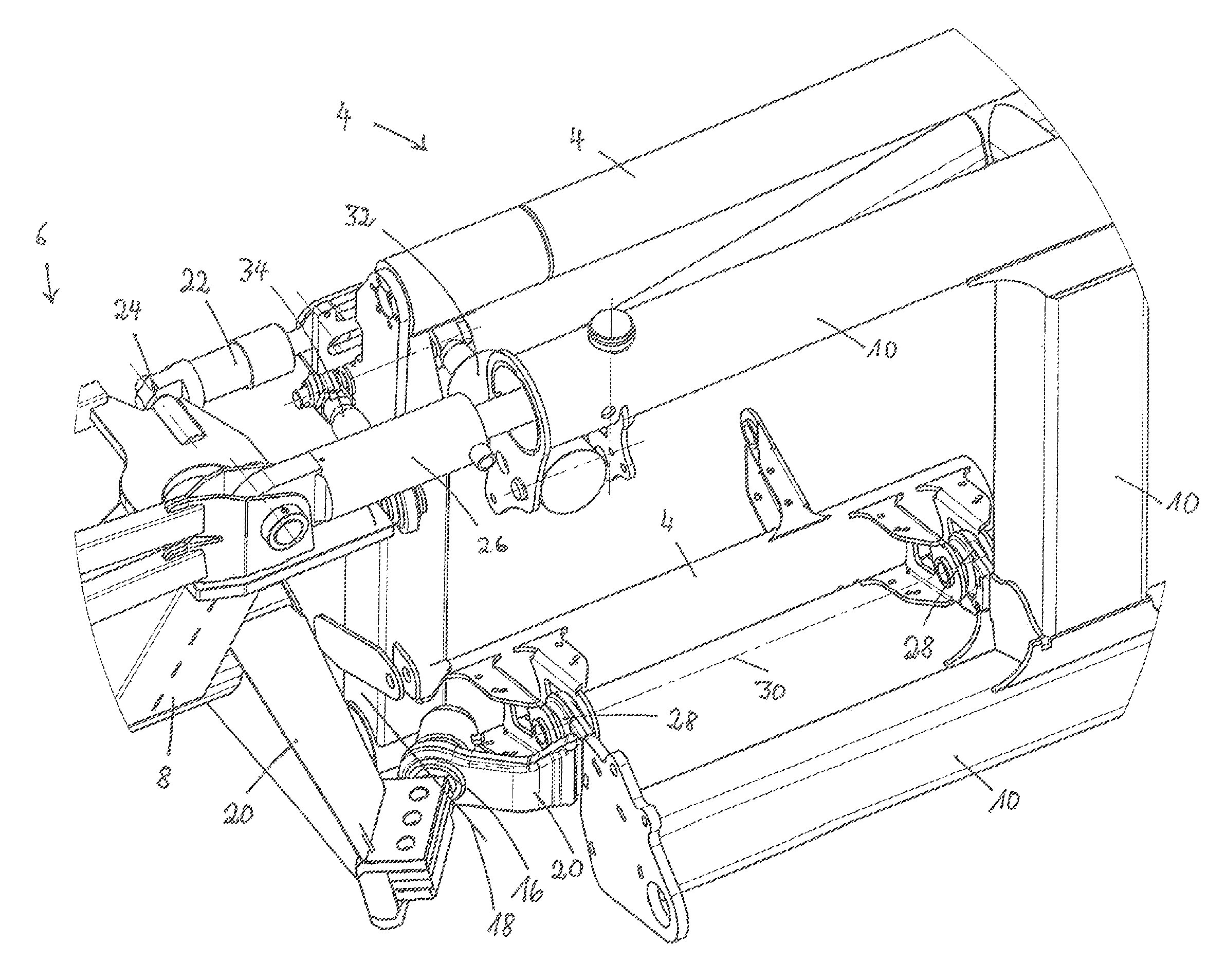
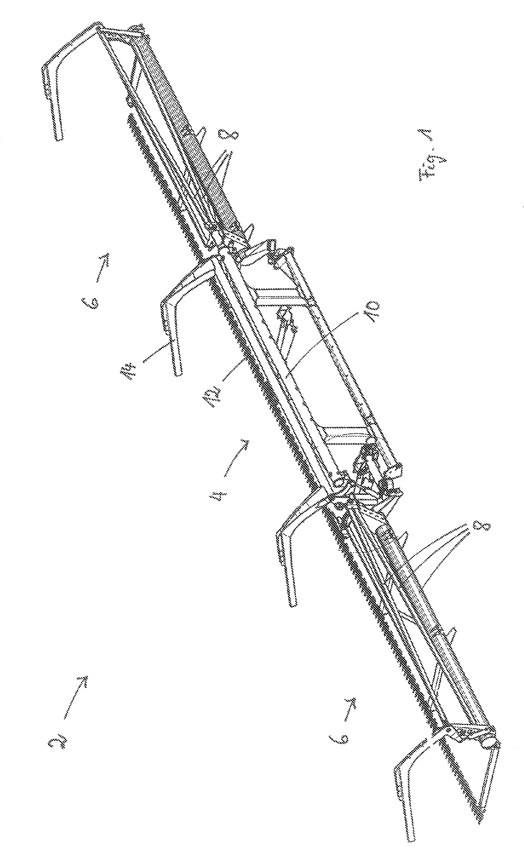
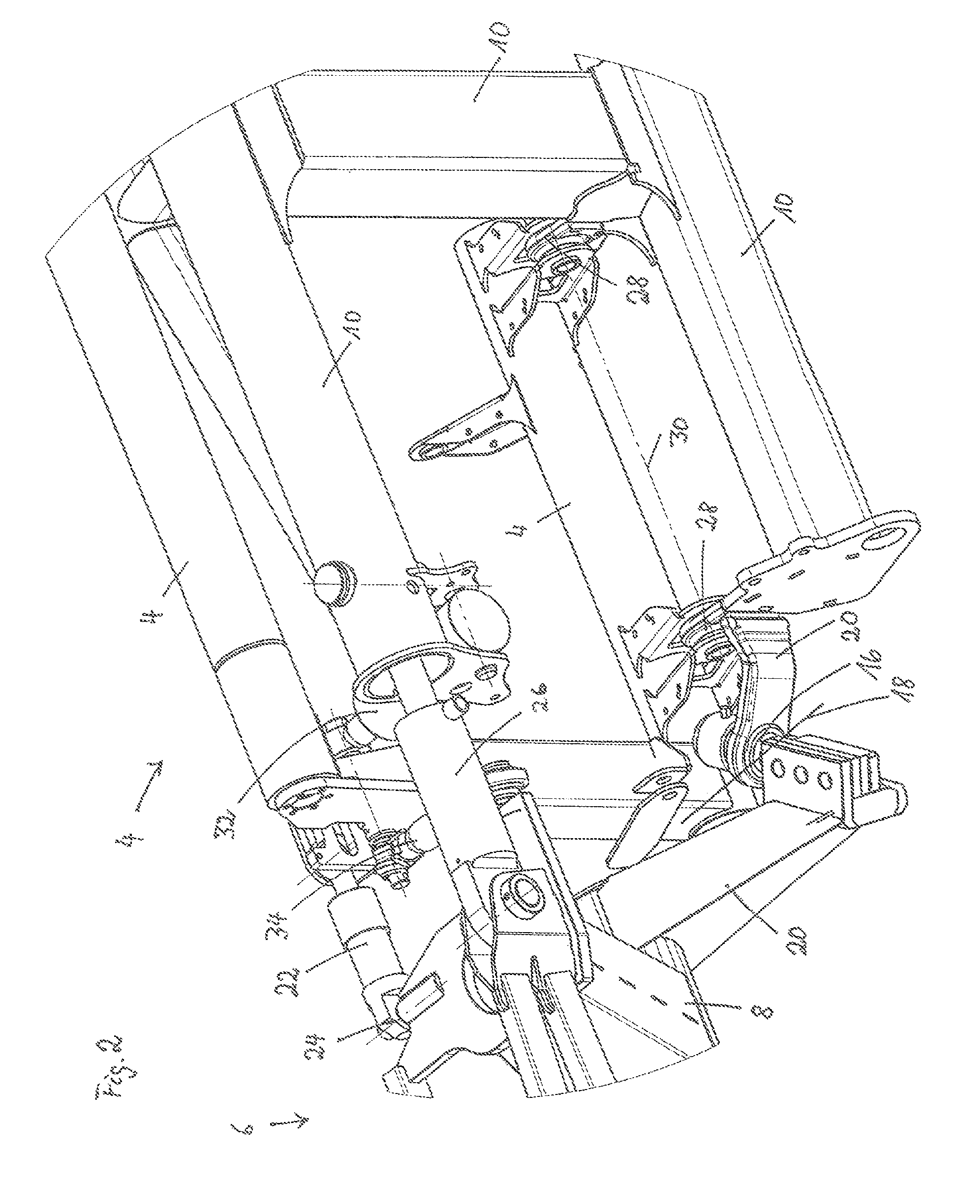
[0021]In FIG. 1, a header 2, viewed in the travel direction of a combine harvester, is shown in a view at a slant from above. The header 2 is comprised in the embodiment of a center part 4 having at both sides a side part 6 each. Each side part 6 comprises a lateral frame 8 which is connected to the attachment frame 10. The attachment frame 10 is designed such that it surrounds the feed channel of a combine harvester, not shown in detail in the drawing, when the header is attached to the combine harvester. By means of the attachment frame 10, the header 2 is thus connected to the feed channel of the combine harvester which supports the header 2 during harvest. At the front end of the header 2, there is a cutter bar 12 with which grain to be harvested is cut.

[0022]For reasons of simplification, in FIG. 1 the conveying elements with which the cut crop is transported toward the center of the header and from there is transferred to the feed channel of the combine harvester are not illus...


PUM


Abstract

A header of a combine harvester has a center part connected by an attachment frame to the combine feed channel. A first side part with first lateral frame and a second side part with second lateral frame are adjustable for changing their position relative to the center part. The first and second lateral frames are connected by a first ball joint and a second ball joint to the attachment frame, respectively so that the weight of the first and second lateral frames is supported by the first and second ball joints on the attachment frame. The first and second ball joints form first and second pivot axes. An end of the first lateral frame facing away from the center part is pivotable about the first pivot axis. An end of the second lateral frame facing away from the center part is pivotable about the second pivot axis.

Description

BACKGROUND OF THE INVENTION[0001]The present invention concerns a multi-part header for attachment to a combine harvester, comprising a center part that is connectable by means of an attachment frame to the feed channel of a combine harvester and at least two side parts each to a corresponding lateral frame whose relative position to the center part is adjustable.[0002]U.S. Pat. No. 4,956,966 discloses a header of the aforementioned kind that is connectable by means of an attachment frame to the feed channel of a combine harvester. The attachment frame is height-adjustably connected to the feed channel in order to be able to guide the header upon forward travel into a grain field at an appropriate spacing to the ground. The attachment frame is additionally pivotable about an axis that extends parallel to the forward travel direction of the combine harvester in order to be able to adjust, in transverse direction, the position of the header relative to the ground contour that is chang...

Claims


Application Information

Patent Timeline
Patent Type & Authority Patents(United States)
IPC IPC(8): A01D41/16A01D41/06
CPCA01D41/16A01D41/06
Inventor SCHULZE RUCKAMP, JAN BERNDSUDHUES, STEFFENTIESSEN, REIMERPOKRIEFKE, MICHAELSONNEN, ROBERTSURMANN, KLEMENS
Owner CARL GERINGHOFF GMBH & CO KG
Why Eureka
Try Eureka