Micro-electro mechanical apparatus with interdigitated spring

a mechanical apparatus and micro-electro technology, applied in the direction of speed/acceleration/shock measurement, measurement devices, instruments, etc., can solve the problems of reducing the tolerance of fabricating errors, reducing accuracy and sensitivity, and excessive stiffness of the conventional spring. the effect of frequency dri

Active Publication Date: 2016-12-27
IND TECH RES INST
View PDF22 Cites 0 Cited by
  • Summary
  • Abstract
  • Description
  • Claims
  • Application Information

AI Technical Summary

Benefits of technology

[0025]The disclosure provides a method for mitigating frequency drift of a micro-electro mechanical apparatus. The method includes using an interdigitated spring to connect at least one mass and an anchor of the micro-electro mechanical apparatus, wherein the interdigitated spring includes a plurality of first folded portions, a plurality of first connecting portions, a plurality of second folded portions, and a plurality of second connecting portions. Each of the first folded portions includes two first spans and a first head portion configured to connect the two first spans. Each of the first connecting portions is respectively connected to the first spans of two adjacent first folded portions to define a first space. Each of the second folding portions includes two second spans and a second head portion configured to connect the two second spans. Each of the second connecting portions is respectively connected to the second spans of two adjacent second folded portions to define a second space. Arranging at least one of the first folded portions in the second space, and arranging at least one of the second folded portions in the first space; and defining the width of the first span which is greater than a critical gap and defining a width of the second span which is greater than a critical gap, wherein the critical gap is located between a movable electrode and a stationary electrode of the micro-electro mechanical apparatus.

Problems solved by technology

However, when a mass of the current micro-electro mechanical inertial sensor is miniaturized, a conventional spring is proportionally scaled-down in a same manner, such that stiffness of the conventional spring is excessively high.
This decreases accuracy and sensitivity.
Thus, a width of the conventional spring becomes smaller, which decreases the tolerance of fabricating error, and induces larger resonance frequency drift.
In the micro-electro mechanical accelerometer, when the mass is scaled-down, it is difficult to reduce the stiffness of the spring.
This is detrimental for sensing small acceleration and decreases the sensitivity of the accelerometer.
When the stiffness of the spring is excessively low, the off-axis acceleration increases the displacement along the sensing axis which decreases the accuracy.
According to the aforementioned examples, it is known that “how to miniaturize the micro-electro mechanical inertia sensors such as an accelerometer, resonator, or gyroscope” has become a critical issue in the development of micro-electro mechanical inertial sensors.

Method used


Image

  • Micro-electro mechanical apparatus with interdigitated spring
  • Micro-electro mechanical apparatus with interdigitated spring
  • Micro-electro mechanical apparatus with interdigitated spring

Examples


first embodiment

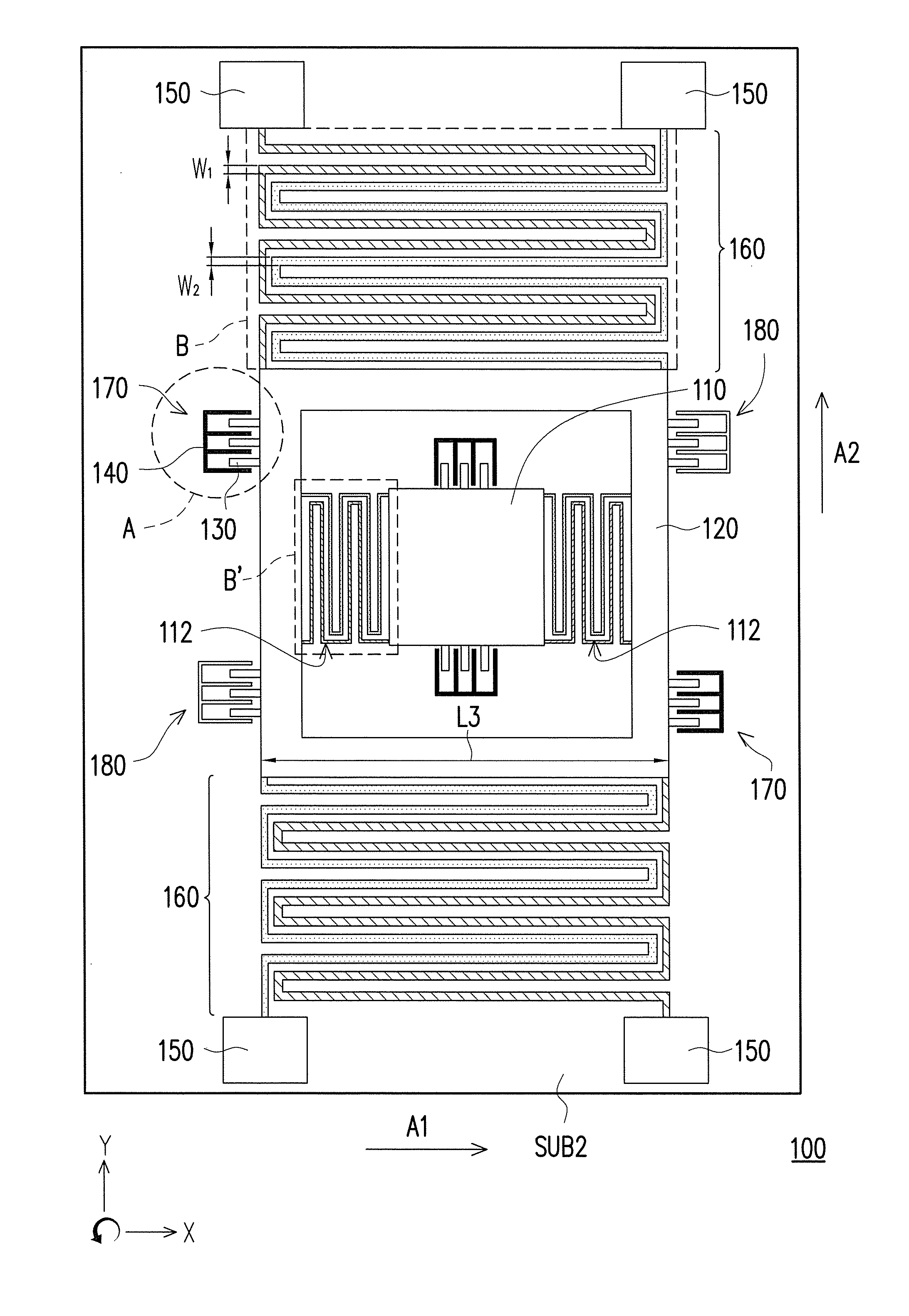
[0054]FIG. 7A is a schematic diagram of a micro-electro mechanical apparatus according to the first embodiment of the disclosure. FIG. 7B is a partial enlarged view of a region A of the micro-electro mechanical apparatus of FIG. 7A. Referring to FIG. 7A, the micro-electro mechanical apparatus 100 is, for example, a micro-electro mechanical gyroscope adapted to sense an angular velocity, and includes a substrate SUB2, a first mass 110, a second mass 120, movable electrodes 130, stationary electrodes 140, anchors 150 and a first interdigitated spring 160.

[0055]The second mass 120 is, for example, a frame structure, the first mass 110 is disposed in the second mass 120, and a second interdigitated spring 112 is connected to the first mass 110 and the second mass 120 along a first axial direction A1. The movable electrodes 130 are disposed at two opposite sides of the second mass 120 along a second axial direction A2. The stationary electrodes 140 are disposed on the substrate SUB2 alon...

second embodiment

[0062]Besides the aforementioned micro-electro mechanical apparatus suitable for sensing angular velocity, the disclosure can also be applied to other types of micro-electro mechanical apparatus. For example, FIG. 8 further illustrates a micro-electro mechanical apparatus adapted to sense acceleration.

[0063]The micro-electro mechanical apparatus 200 of FIG. 8 includes a substrate SUB3, a first mass 210, movable electrodes 220, stationary electrodes 230, anchors 240 and an interdigitated spring 250. The movable electrodes 220 are disposed on the first mass 210 along the first axial direction A1. The stationary electrodes 230 are disposed on the substrate SUB3 along the first axial direction A1, where the stationary electrode 230 and the movable electrode 220 form a sensing electrode 260. The movable electrode 220 of the sensing electrode 260 and the stationary electrode 230 of the sensing electrode 260 have a critical gap there between, and the critical gap is formed between the mova...

third embodiment

[0067]FIG. 9 illustrates another micro-electro mechanical apparatus using the aforementioned interdigitated spring and bridges. In detail, the micro-electro mechanical apparatus 300 of FIG. 9 is, for example, a micro-electro mechanical resonator, and includes a substrate SUB4, a first mass 310, movable electrodes 320, stationary electrodes 330, anchors 340 and an interdigitated spring 350.

[0068]In the present embodiment, the movable electrodes 320 are, for example, disposed on the first mass 310 along the first axial direction A1. The stationary electrodes 330 are, for example, disposed on the substrate SUB4 along the first axial direction A1, where the stationary electrodes 330 and the movable electrodes 320 form a sensing electrode 360 and a driving electrode 370. The movable electrode 320 of the sensing electrode 360 and the stationary electrode 330 of the sensing electrode 360 have a critical gap there between, and the critical gap is formed between the movable electrode 320 and...


PUM


Abstract

A micro-electro mechanical apparatus with interdigitated spring including a substrate, at least one first mass, a movable electrode, a stationary electrode, an anchor and an interdigitated spring is provided. The movable electrode is disposed on the mass along an axial direction. The stationary electrode is disposed on the substrate along the axial direction, and the movable electrode and the stationary electrode have a critical gap there between. The interdigitated springs connects the mass and the anchor along the axial direction. The interdigitated spring includes first folded portions, first connecting portions, second folded portions, and second connecting portions. Each first folded portion includes two first spans and a first head portion. Each second folded portion includes two second spans and a second head portion. A width of the first span and a width of the second span are greater than the critical gap respectively.

Description

CROSS-REFERENCE TO RELATED APPLICATION[0001]This application claims the priority benefit of Taiwan application serial no. 102107354, filed on Mar. 1, 2013. The entirety of the above-mentioned patent application is hereby incorporated by reference herein and made a part of this specification.BACKGROUND[0002]Technical Field[0003]The disclosure relates to a micro-electro mechanical apparatus. Particularly, the disclosure relates to a micro-electro mechanical apparatus with interdigitated spring.[0004]Related Art[0005]In recent years, with the development of electronic products such as smart phones, tablet PCs, game consoles, etc., micro-electro mechanical inertial sensors such as accelerometers, gyroscopes, oscillators, etc. are widely used in the aforementioned electronic products. The market for these products has significantly increased each year. Currently, techniques of the micro-electro mechanical inertial sensors have gradually matured, and the miniaturization, high on-axis sens...

Claims


Application Information

Patent Timeline
Patent Type & Authority Patents(United States)
IPC IPC(8): G01P15/08G01P15/125
CPCG01P15/125G01P2015/0814G01P2015/0857
Inventor LIN, SHIH-CHIEHHUANG, CHAO-TASU, CHUNG-YUANHSU, YU-WEN
Owner IND TECH RES INST
Why Eureka
Try Eureka