Adjustable high-stable F-P integrated endoscope device

A F-P, high stability technology, applied in the structure/shape of the optical resonator, can solve the problems of optical path closed spectral line intensity output, adverse effects of fineness, inability to conveniently place the sample cell in the cavity, and inability to provide mechanical structures, etc. Achieve the effects of reducing spectral line frequency drift, simple structure, and high signal-to-noise ratio

Inactive Publication Date: 2013-12-18
NAT TIME SERVICE CENT CHINESE ACAD OF SCI
View PDF8 Cites 0 Cited by
  • Summary
  • Abstract
  • Description
  • Claims
  • Application Information

AI Technical Summary

Problems solved by technology

However, there are still some problems in this integral F-P cavity: on the one hand, although its stability is better than that of the open F-P cavity, its adjustable degree is greatly limited, and the optical path closure of the light depends largely on the operator to paste the lens experience, to achieve the absolute parallelism of the two lenses, which is a great challenge for the operator
And because of the adhesive method, it is a one-time process. If there is an angle problem between the pasted lenses, the glue needs to be removed and the operation repeated, which makes the experimental operation complicated and time-consuming.
On the other hand, although the design of cavity integration ensures that the axial centers of the two plano-concave lenses are consistent, the result of such axial center consistency is only established before the lower end cover is rotated. When the cavity matching needs to be carried out in the experiment When the lower end cap is rotated, the center position of the plano-concave lens in the central area of ​​the lower end cap changes with the rotation thread, which destroys its consistency with the plano-concave lens of the upper end cap on the axial center. both adversely affect
In addition, for the physical experiment of the absorption detection of the sample cell, the open optical F-P cavity cannot provide a loading device with a stable mechanical structure and an absolutely consistent optical center, while the integral optical F-P cavity cannot conveniently place the sample cell in the cavity due to structural limitations. And once the overall F-P cavity has closed the optical path and the lens is fixed, the sample in the cavity cannot be taken out from the closed cavity, which will bring difficulties to further operations in the later stage, such as temperature control of the sample cell, position adjustment, etc.

Method used


Image

  • Adjustable high-stable F-P integrated endoscope device
  • Adjustable high-stable F-P integrated endoscope device
  • Adjustable high-stable F-P integrated endoscope device

Examples


Embodiment 1

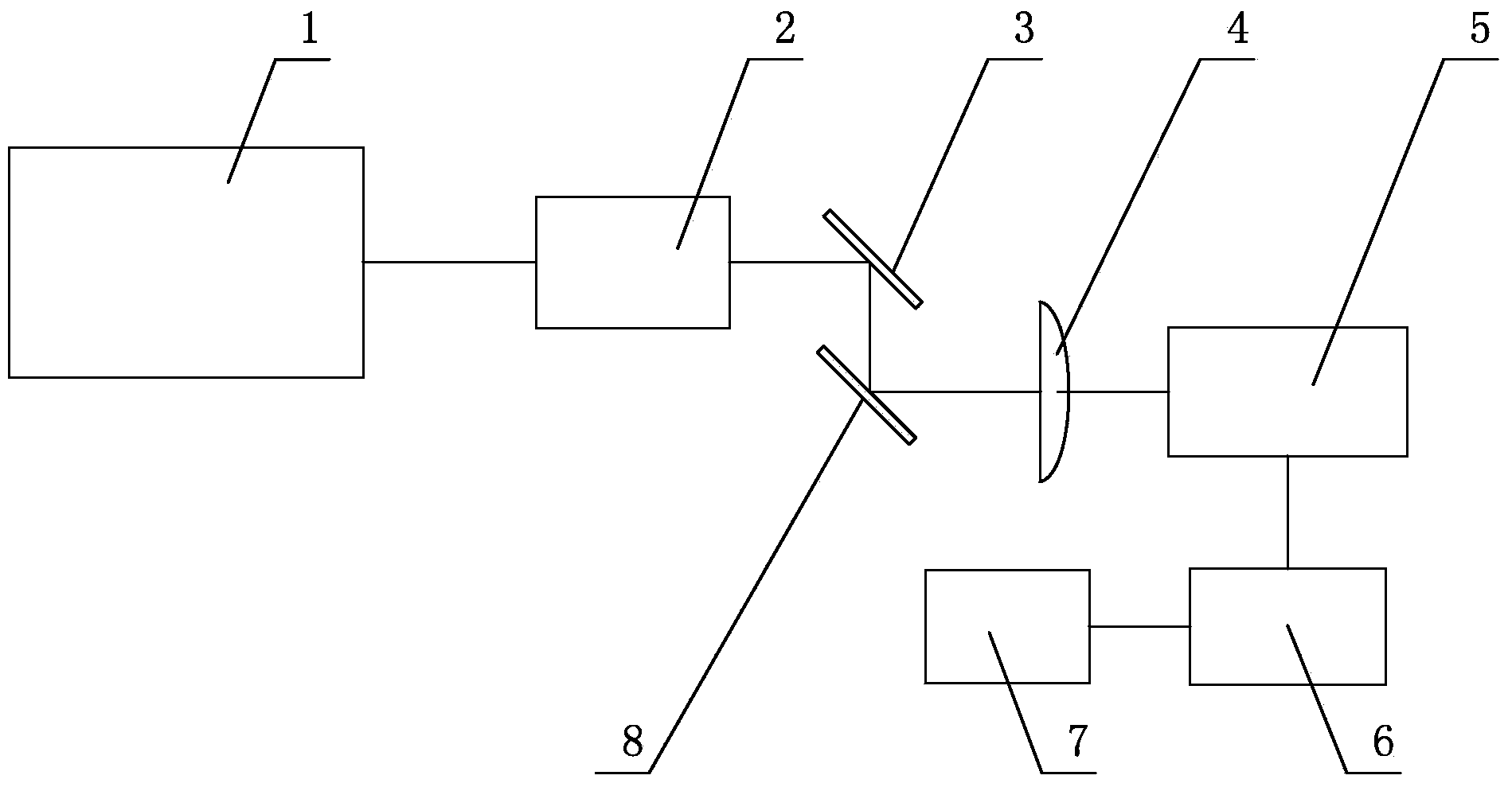
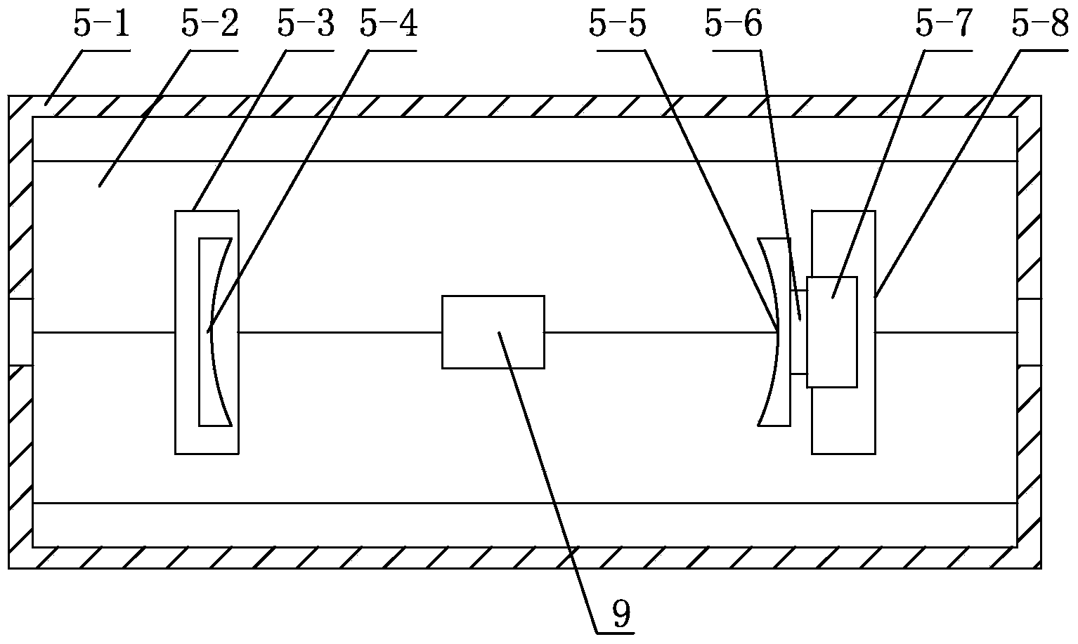
[0024] Depend on figure 1 It can be seen that the adjustable F-P integral cavity device of this embodiment is connected by a light source 1, an optical isolator 2, a first plane mirror 3, a matching lens 4, an F-P integral cavity mirror group 5, a high-voltage amplifier 6, a signal source 7, and a second plane mirror 8 constitute.

[0025] The laser of this embodiment is used as a light source 1, and emits laser light with a wavelength of 633nm. An optical isolator 2 is installed at a position 10mm away from the laser on the outgoing optical path of the laser light. The center wavelength of the optical isolator 2 is 650nm, and the applicable wavelength range is 630 to 700nm. , the transmittance is 75%, and the isolation is 30dB. A reflective plane mirror group is installed at a position 220 mm away from the optical isolator on the exit light path of the optical isolator 2 to adjust the optical center of the laser light path. The reflective plane mirror group includes the first...

Embodiment 2

[0030] The laser of this embodiment is used as a light source 1 to emit laser light, and an optical isolator 2 is installed at a position 10 mm away from the laser on the outgoing light path of the laser light, and a reflective flat mirror is installed at a position 220 mm away from the optical isolator on the outgoing light path of the optical isolator 2 group, the reflective plane mirror group includes a first plane mirror 3 and a second plane mirror 8, the first plane mirror 3 is installed on the exit light path of the optical isolator 2 and forms an included angle of 45° with the exit light path, and the second plane mirror 8 is installed on Directly below the first plane mirror 3, parallel to the first plane mirror 3, the center distance between the first plane mirror 3 and the second plane mirror 8 is 20mm, the light is reflected from the first plane mirror 3 to the second plane mirror 8, and then from the second plane mirror 8 is reflected, on the reflected optical path ...

Embodiment 3

[0035] The laser of this embodiment is used as a light source 1 to emit laser light, and an optical isolator 2 is installed at a position 10 mm away from the laser on the outgoing light path of the laser light, and a reflective flat mirror is installed at a position 220 mm away from the optical isolator on the outgoing light path of the optical isolator 2 group, the reflective plane mirror group includes a first plane mirror 3 and a second plane mirror 8, the first plane mirror 3 is installed on the exit light path of the optical isolator 2 and forms an included angle of 45° with the exit light path, and the second plane mirror 8 is installed on Directly below the first plane mirror 3, parallel to the first plane mirror 3, the center distance between the first plane mirror 3 and the second plane mirror 8 is 80mm, and the light is reflected from the first plane mirror 3 to the second plane mirror 8, and then from the second plane mirror 8 is reflected, and on the reflected light...


PUM

PropertyMeasurementUnit
Angleaaaaaaaaaa
Isolationaaaaaaaaaa

Abstract

The invention relates to an adjustable high-stable F-P integrated endoscope device which comprises a signal source, a high-voltage amplifier, a light source, an optical separator, a reflective plane mirror set, a matching lens and an F-P integrated endoscope set. The high-voltage amplifier and the light source are connected with the signal source. The optical separator and the reflective plane mirror set are sequentially arranged on an emergent light path of the light source. The matching lens and the F-P integrated endoscope set are sequentially arranged on a reflected light path of the reflective plane mirror set. The frequency variations of spectral lines can be greatly reduced, according to the F-P integrated endoscope set, lens mounts for fixing a first plano-concave lens and a second plano-concave lens are fixed in a V-shaped groove in the top of a base, therefore, the free degree of the lens mounts is greatly reduced, the direction of horizontal moving is also limited, and stability and sensitivity and precision of detection of the lens set are greatly improved. The purpose of convenient adjusting is achieved, besides, the requirement for the stability is met, operation is convenient, the structure is simple, and the simple tool is provided for a related physical experiment.

Description

technical field [0001] The invention belongs to the technical field of optical devices, and in particular relates to an adjustable and highly stable F-P integral cavity device. Background technique [0002] Fabry-Perot cavity (F-P cavity) is a physical device commonly used in spectroscopy experiments. On the one hand, it is used as an etalon for spectral line frequency calibration; on the other hand, it is used as one of the main tools for generating frequency discrimination standard signals. One is used for laser frequency locking, especially for semiconductor lasers often used in atomic physics experiments. In addition to the above applications, in particular, it can also be used for intracavity absorption experiments to optimize the absorption signal. [0003] The method is to place the sample cell (or absorbing substance) in the cavity, inject laser light into the cavity, and the light is reflected multiple times by two high-reflectivity mirrors in the cavity. The equiv...

Claims


Application Information

Patent Timeline
IPC IPC(8): H01S3/08
Inventor 田晓常宏
Owner NAT TIME SERVICE CENT CHINESE ACAD OF SCI
Why Eureka
Try Eureka