Supercharge Your Innovation With Domain-Expert AI Agents!

Test path compensating circuit and test path compensating system

a compensation circuit and path technology, applied in the direction of electronic circuit testing, measurement devices, instruments, etc., can solve problems such as preventing the acquisition of precise testing

Active Publication Date: 2017-01-03
SK HYNIX INC
View PDF6 Cites 0 Cited by
  • Summary
  • Abstract
  • Description
  • Claims
  • Application Information

AI Technical Summary

Benefits of technology

The patent describes a test path compensating circuit and system that can improve the accuracy of testing electronic circuits. The circuit includes multiple electrical paths that connect test pads to a test target circuit, and a control voltage generation circuit that produces multiple control voltages. The circuit also has multiple voltage-control delay circuits that use the control voltages to delay the input test signals and provide the delayed signals as output signals to the test target circuit. The circuit can compensate for variations in the electrical path delay caused by changes in input test signals and external factors, resulting in more accurate testing of electronic circuits.

Problems solved by technology

In devices scaled down, such time differences may impede the acquisition of a precise testing result.

Method used


Image

  • Test path compensating circuit and test path compensating system
  • Test path compensating circuit and test path compensating system
  • Test path compensating circuit and test path compensating system

Examples


Embodiment Construction

[0016]Hereinafter, a test path compensating circuit and a test path compensating system will be described below with reference to the accompanying drawings through various examples of embodiments.

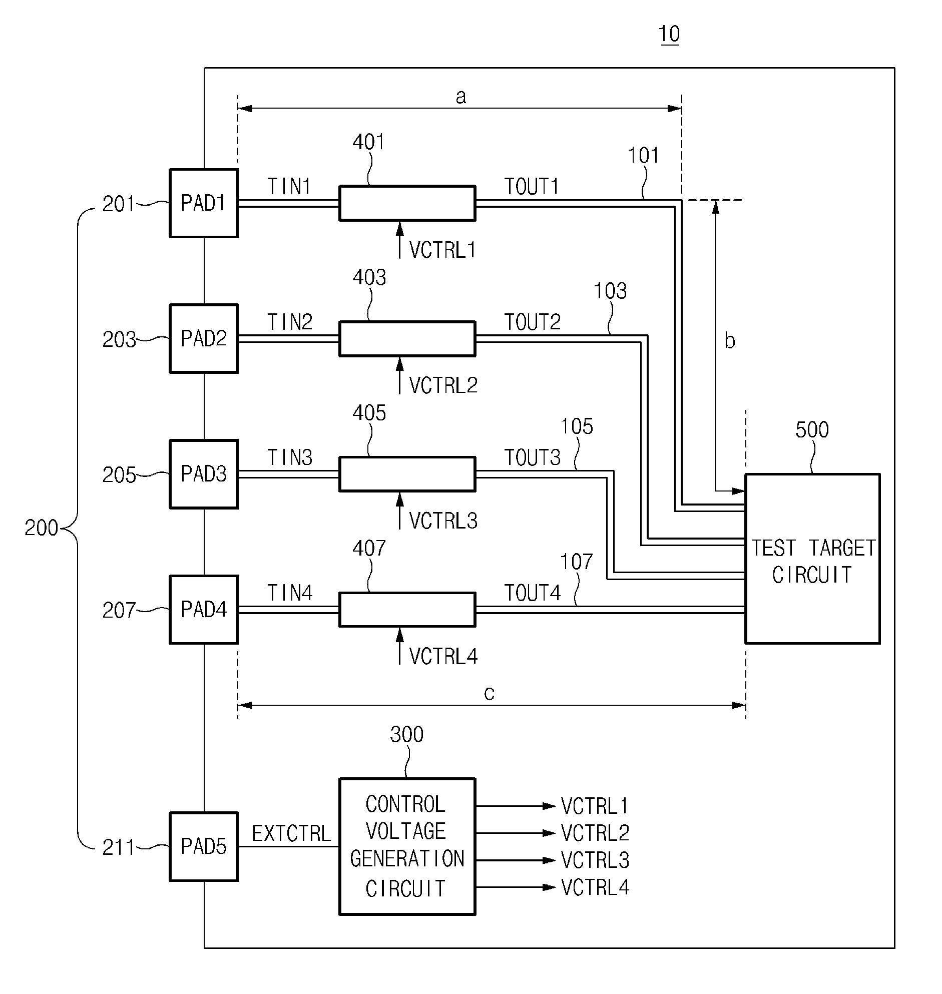
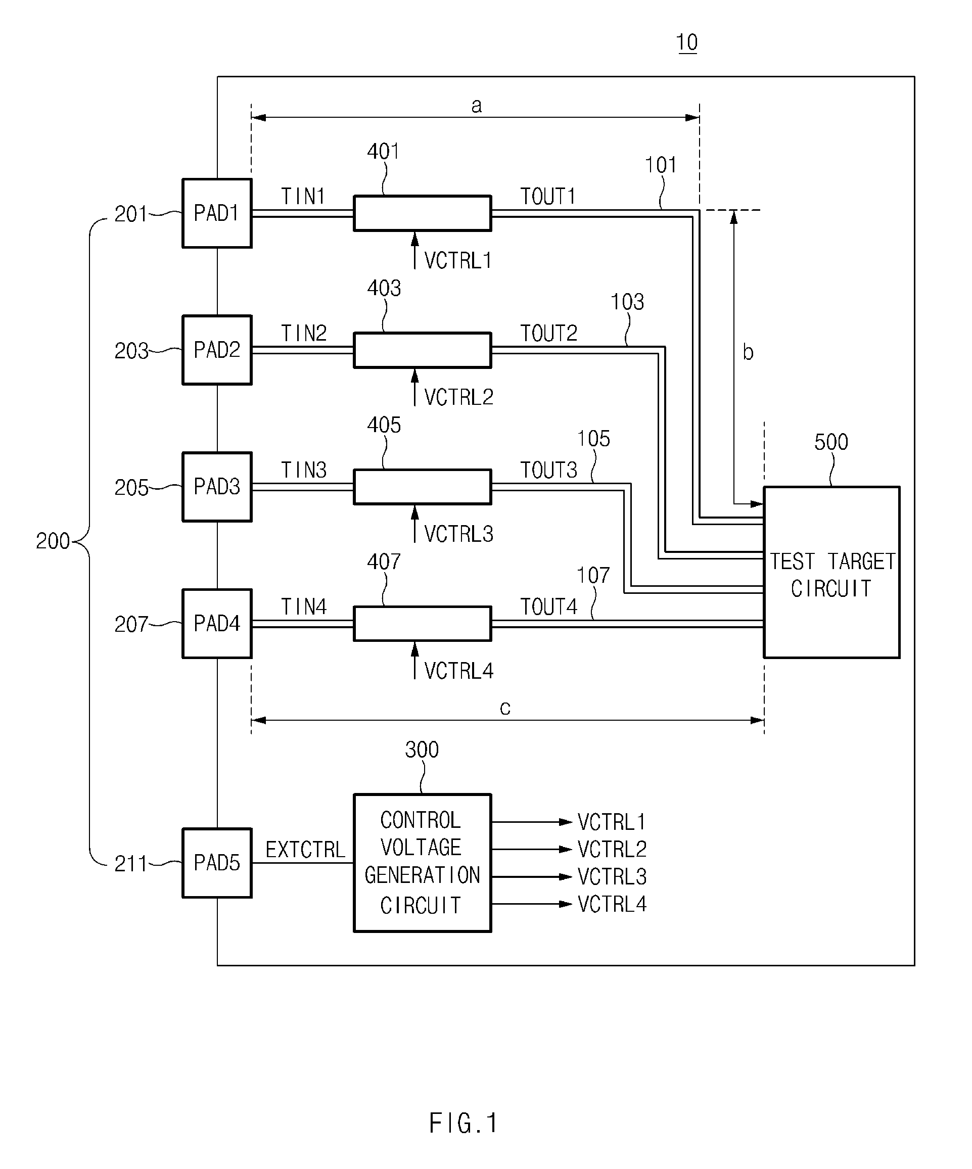
[0017]Various embodiments may be directed to a test path compensating circuit and a test path compensating system for finely controlling differences in electrical paths extending from a plurality of test pads to a target circuit to be tested.

[0018]Various embodiments may be directed to a test path compensating circuit and a test path compensating system for compensating for differences in electrical paths extending from test pads to a target circuit to be tested, through a simple configuration.

[0019]In the test path compensating circuit and the test path compensating system according to the embodiments, since the delay amounts of input test signals may be linearly controlled through analog circuits, fine delay amount control may be capable.

[0020]In the test path compensating circuit and the...


PUM


Abstract

A test path compensating circuit may include a plurality of electrical paths electrically coupling a plurality of test pads to a test target circuit. The test path compensating circuit may include a control voltage generation circuit configured to generate a plurality of control voltages. The test path compensating circuit may include a plurality of voltage-control delay circuits electrically coupled to the plurality of electrical paths, respectively, and configured to control delay amounts of input test signals received from one or more of the plurality of test pads, based on one or more of the plurality of control voltages, and provide output test signals to the test target circuit.

Description

CROSS-REFERENCES TO RELATED APPLICATION[0001]The present application claims priority under 35 U.S.C. §119(a) to Korean application number 10-2014-0142088, filed on Oct. 20, 2014, in the Korean Intellectual Property Office, which is incorporated herein by reference in its entirety.BACKGROUND[0002]1. Technical Field[0003]Various embodiments generally relate to a test path compensating circuit and a test path compensating system, and more particularly, to a test path compensating circuit and a test path compensating system for compensating for the paths of input test signals received through test pads, to perform a test.[0004]2. Related Art[0005]As the demand toward electronic devices increases, especially with devices that are convenient for carrying, so does the need to have the component elements and devices disposed within the electronic devices scaled down. The component elements disposed in the electronic devices are electrically coupled through electrical paths. The Electrical p...

Claims


Application Information

Patent Timeline
Patent Type & Authority Patents(United States)
IPC IPC(8): G01R31/319G01R31/317G11C29/12G11C29/48G01R31/30G01R31/3193
CPCG01R31/31924G01R31/31726G01R31/31937G11C29/1201G11C29/48
Inventor LEE, SEONG JU
Owner SK HYNIX INC
Features
  • R&D
  • Intellectual Property
  • Life Sciences
  • Materials
  • Tech Scout
  • Unparalleled Data Quality
  • Higher Quality Content
  • 60% Fewer Hallucinations
Learn More