
Cloud enabled building automation system

a building automation and cloud technology, applied in the direction of electric programme control, program control, instruments, etc., can solve the problems of inability to control the environment settings of the occupants of the building, system cost effectiveness or energy efficiency, and strategies that do not consider changes in energy prices, etc., to achieve optimized energy use and cost optimization

Active Publication Date: 2017-01-03
SIEMENS AG
View PDF32 Cites 17 Cited by
  • Summary
  • Abstract
  • Description
  • Claims
  • Application Information

AI Technical Summary

Benefits of technology

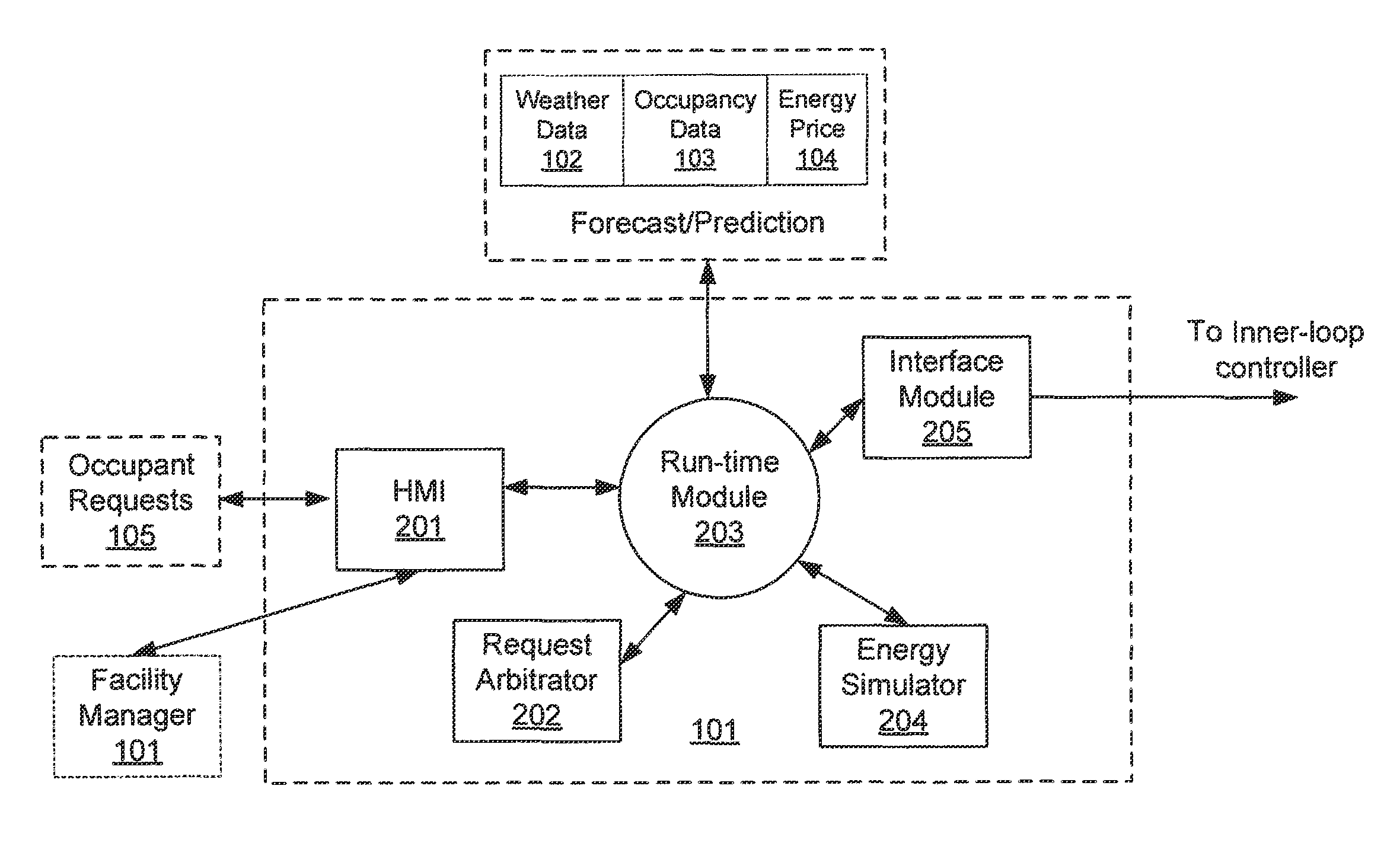
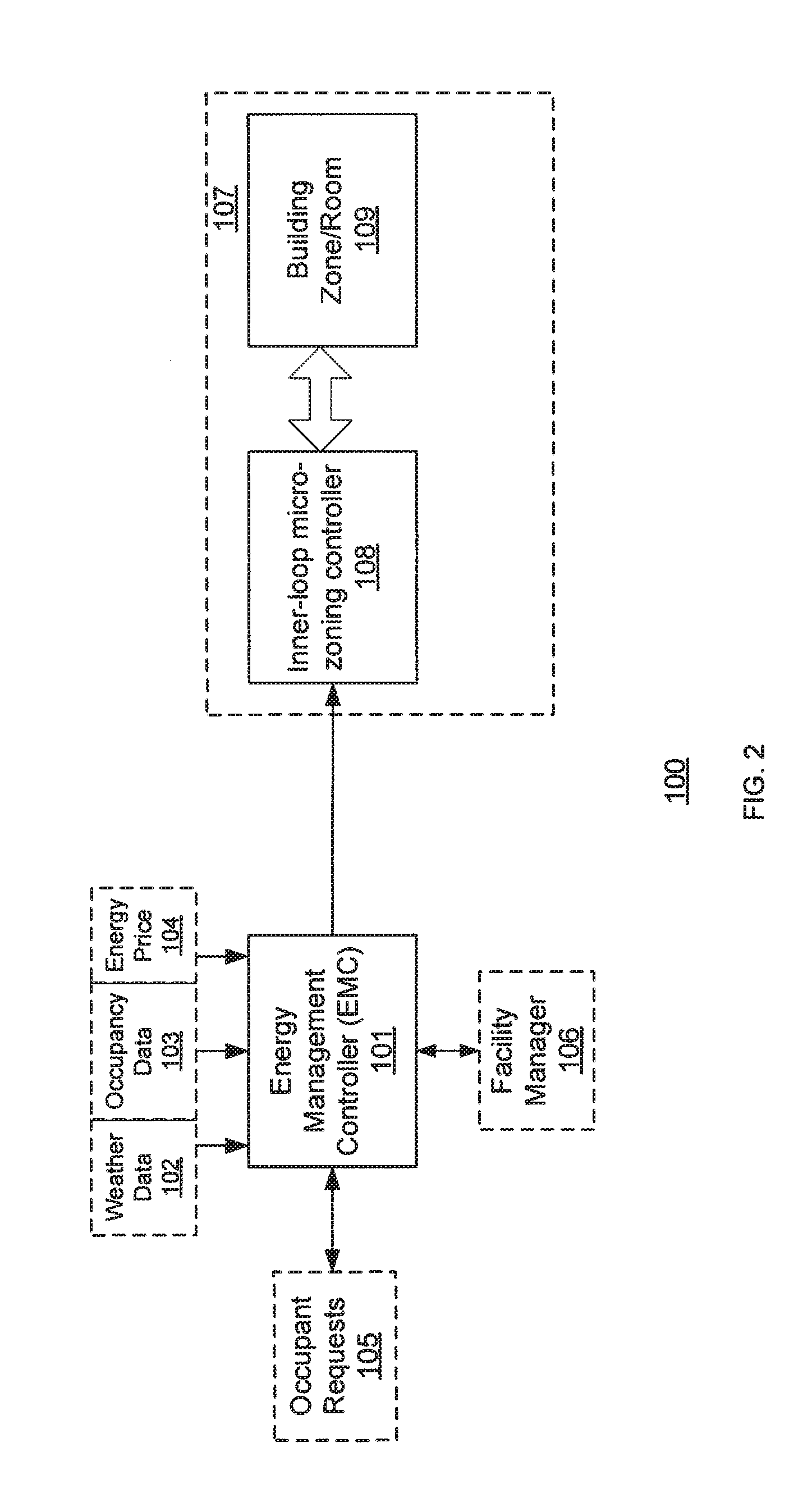
The patent describes a method to control energy consumption in a building by using a cloud computing platform to receive occupant requests, weather data, and a facility management rule. The platform generates output control signals based on these requests, weather data, and the facility management rule to optimize energy use and cost. The technical effect is to provide a more efficient and cost-effective way to manage energy consumption in buildings.

Problems solved by technology

However, such strategies do not consider changes in energy prices, such as the price of electricity, which occur at different times and for different weather conditions.
Thus, such systems are not cost effective or energy efficient.
Another disadvantage is that occupants in the building may not be able to control their own environment settings.

Method used


Image

  • Cloud enabled building automation system
  • Cloud enabled building automation system
  • Cloud enabled building automation system

Examples


Embodiment Construction

[0015]Before any embodiments of the invention are explained in detail, it is to be understood that the invention is not limited in its application to the details of construction and the arrangement of components set forth in the following description or illustrated in the following drawings. The invention is capable of other embodiments and of being practiced or of being carried out in various ways. Also, it is to be understood that the phraseology and terminology used herein is for the purpose of description and should not be regarded as limiting. The use of “including,”“comprising,” or “having” and variations thereof herein is meant to encompass the items listed thereafter and equivalents thereof as well as additional items. Unless specified or limited otherwise, the terms “mounted,”“connected,”“supported,” and “coupled” and variations thereof are used broadly and encompass direct and indirect mountings, connections, supports, and couplings. Further, “connected” and “coupled” are ...


PUM


Abstract

A method of controlling energy consumption in a building. The method includes receiving occupant request data including a plurality of requests, wherein each of the plurality of requests corresponds to one of a plurality of zones in the building wherein the occupant request data is received via a cloud computing resource. The method also includes receiving weather data including at least one of current weather measurement data and weather forecast data wherein the weather data is received via a cloud computing resource. In addition, a facility management rule is received via a cloud computing resource. Further, the method includes generating a plurality of output control signals via cloud computing resource, wherein each of the plurality of output control signals is based on one of a plurality of requests and predicted occupant schedules, energy price data and the facility management rule. The control signals are generated by using simulation-based model predictive control method to determine a set of optimized control signals based on optimized energy use or optimized energy cost. The optimized control signals are transmitted to controllers.

Description

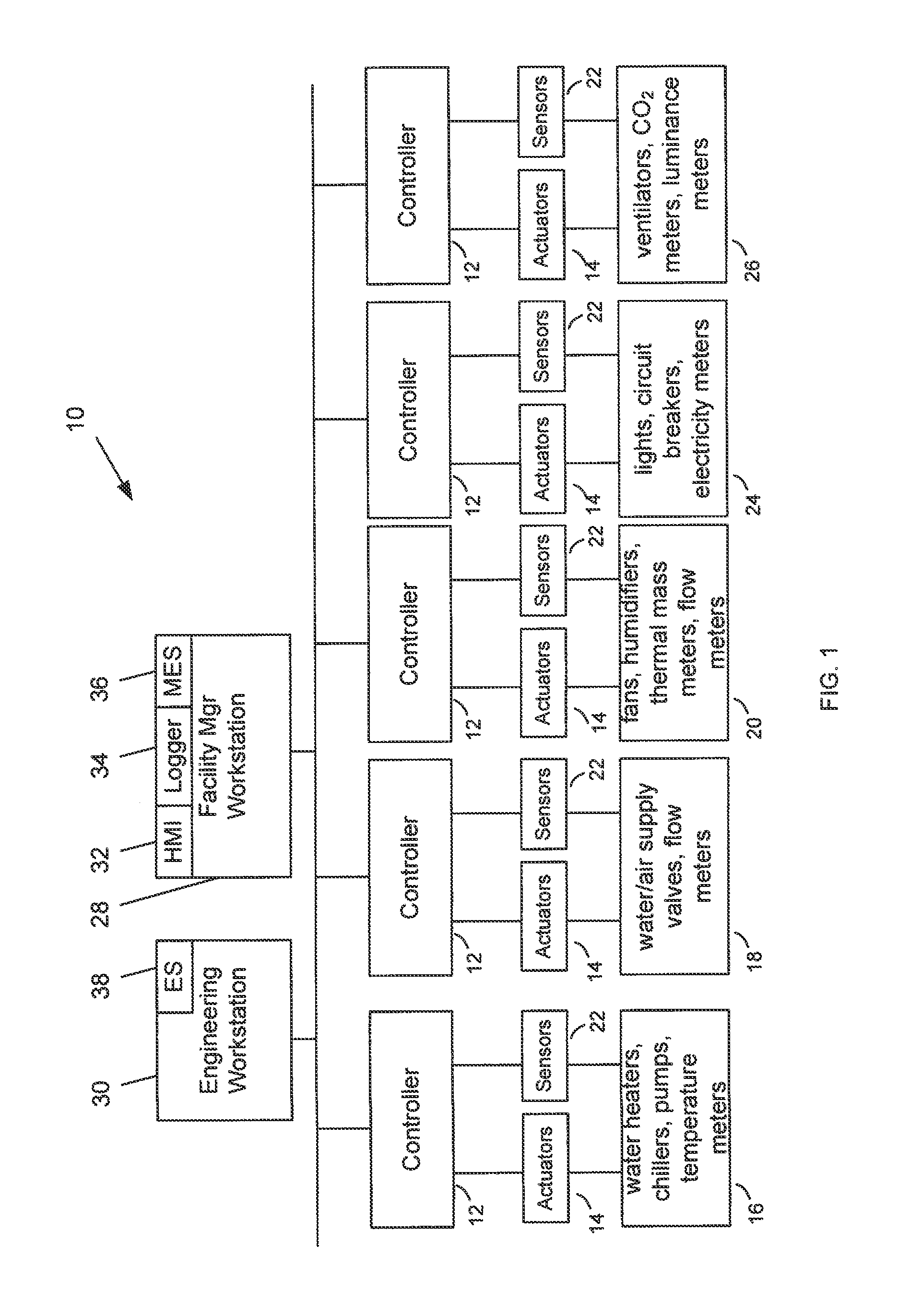
CROSS REFERENCE TO RELATED APPLICATION[0001]This application is a continuation-in-part application of U.S. application Ser. No. 13 / 763,870 filed on Feb. 11, 2013 entitled SYSTEM AND METHOD OF ENERGY MANAGEMENT CONTROL which claims the benefit under 35 U.S.C. 119(e) of U.S. Provisional Application No. 61 / 606,630 filed on Mar. 5, 2012 wherein both applications are hereby incorporated by reference in their entirety.FIELD OF THE INVENTION[0002]This invention to energy management control, and more particularly, to a cloud enabled energy management control framework to provide optimized control and operation for energy efficient buildings.BACKGROUND OF THE INVENTION[0003]Many current building automation systems use reactive control strategies to monitor and control various systems in a building. For example, the strategies may include following schedules and settings created by a facility manager. Referring to FIG. 1, an architecture 10 for a reactive building automation system is shown. ...

Claims


Application Information

Patent Timeline
Patent Type & Authority Patents(United States)
IPC IPC(8): G05B19/02G05B15/02G06Q50/06
CPCG05B19/02G05B15/02G06Q50/06G05B2219/2642
Inventor WEI, DONGDARIE, FLORINJI, KUNSONG, ZHEN
Owner SIEMENS AG
Learn More