Inline air treatment device

a technology of air treatment device and inline ductwork, which is applied in the direction of lighting and heating apparatus, heating types, transportation and packaging, etc., can solve the problems of obstructing airflow, inefficient air treatment, and high installation cost of existing inline ductwork odor management system, so as to increase the power demand of blowing components, increase maintenance costs, and increase installation costs

Active Publication Date: 2017-01-10
EIKE MASON EDWARD
View PDF42 Cites 1 Cited by
  • Summary
  • Abstract
  • Description
  • Claims
  • Application Information

AI Technical Summary

Benefits of technology

[0006]Existing inline ductwork odor management systems are generally expensive to install, are prone to maintenance that requires expensive replacement parts, and inefficiently treat the air leading to sub-optimal levels of odor neutralization and / or elimination. For instance, some existing odor management devices (e.g., including odor neutralizing agents) are physically placed across the airflow path of the ductwork which necessarily obstructs the airflow and increases the power demands of the blowing componentry. Oftentimes, disassembly of these devices is required which adds wear to system components, adds weight if being suspended in the air for mounting purposes and can result in undesirable air being present where the disassembly occurs. Physical obstruction of the airflow and / or sagging of the ductwork due to the suspended componentry ultimately leads to inefficient airflow, unneeded recurring labor, and increased maintenance costs.
[0007]As another example, some odor management devices require supplemental electrical components and power to operate (e.g., independent of that of an HVAC system), such as electrically powered dispensing agent. However, some of these agents can break down causing particles to travel throughout an HVAC system leading to an increased risk of damage to downstream ventilation components as well as fire hazards. Furthermore, supplement power requirements increase overall energy consumption by the home, building, etc.
[0009]As just one example, an existing duct of an air handling system may be appropriately separated (e.g., split, cut, etc.) into first and second duct members having respective open ends. The respective open ends of the first and second duct members may then be appropriately secured (e.g., with hose clamps or the like) over the first and second openings of the airflow treatment device so that the airflow passageway extends through the first duct member, the first and second openings of the device, and the second duct member. In one arrangement, the airflow treatment device may be appropriately hung from or otherwise secured to a fixed member (e.g., structural member of the house or building, such as a joist, etc.) at a point above the first and second duct members to limit or otherwise reduce the load placed on the ductwork by the airflow treatment device. As just one example, the airflow treatment device may have a first connector member (e.g., hole, hook, opening, etc.) that is configured to connect with a corresponding second connector member (e.g., hook, hole, etc.) on a joist or other fixed member of the house or building.

Problems solved by technology

Existing inline ductwork odor management systems are generally expensive to install, are prone to maintenance that requires expensive replacement parts, and inefficiently treat the air leading to sub-optimal levels of odor neutralization and / or elimination.
For instance, some existing odor management devices (e.g., including odor neutralizing agents) are physically placed across the airflow path of the ductwork which necessarily obstructs the airflow and increases the power demands of the blowing componentry.
Oftentimes, disassembly of these devices is required which adds wear to system components, adds weight if being suspended in the air for mounting purposes and can result in undesirable air being present where the disassembly occurs.
Physical obstruction of the airflow and / or sagging of the ductwork due to the suspended componentry ultimately leads to inefficient airflow, unneeded recurring labor, and increased maintenance costs.
However, some of these agents can break down causing particles to travel throughout an HVAC system leading to an increased risk of damage to downstream ventilation components as well as fire hazards.
Furthermore, supplement power requirements increase overall energy consumption by the home, building, etc.

Method used


Image

  • Inline air treatment device
  • Inline air treatment device
  • Inline air treatment device

Examples


Embodiment Construction

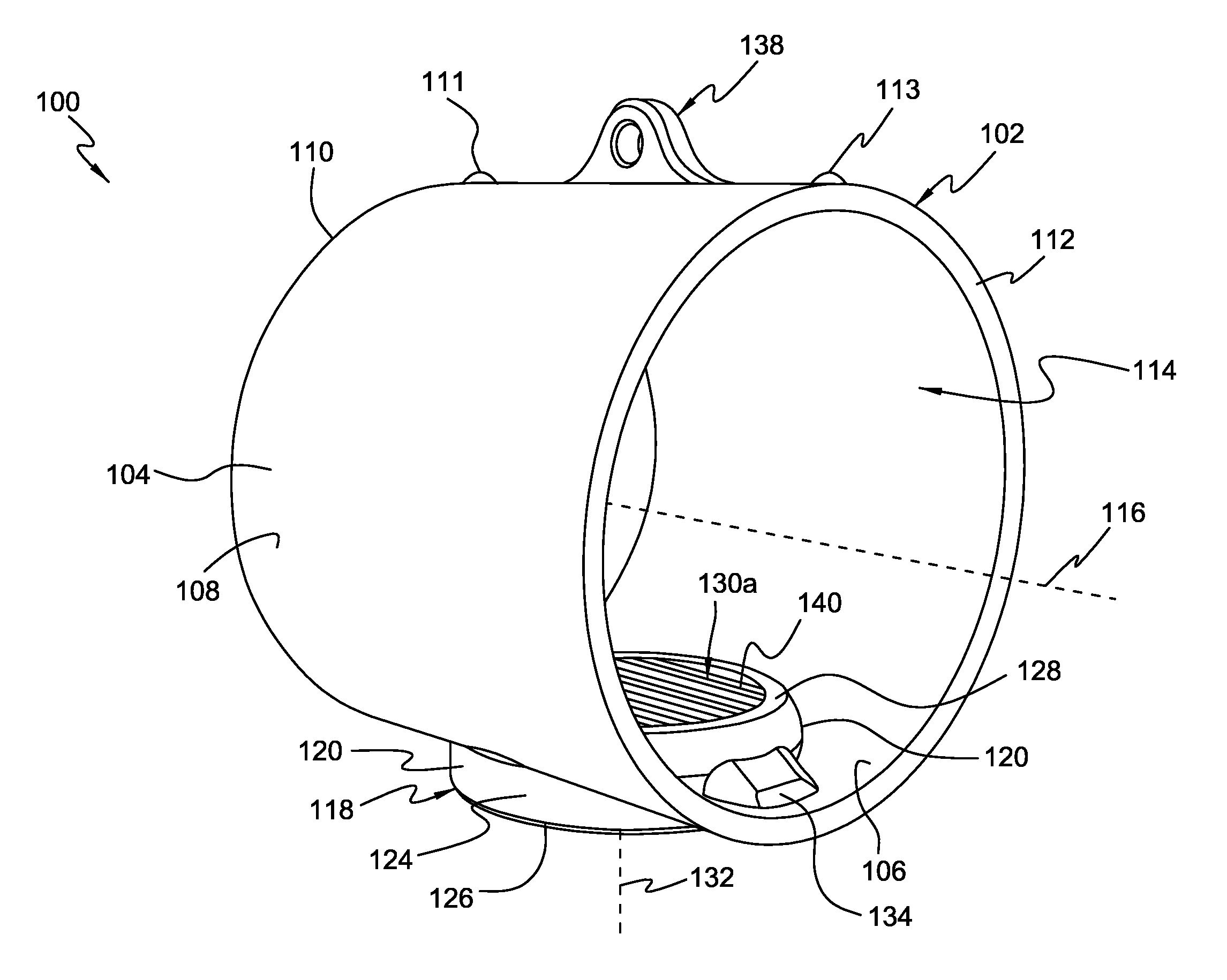
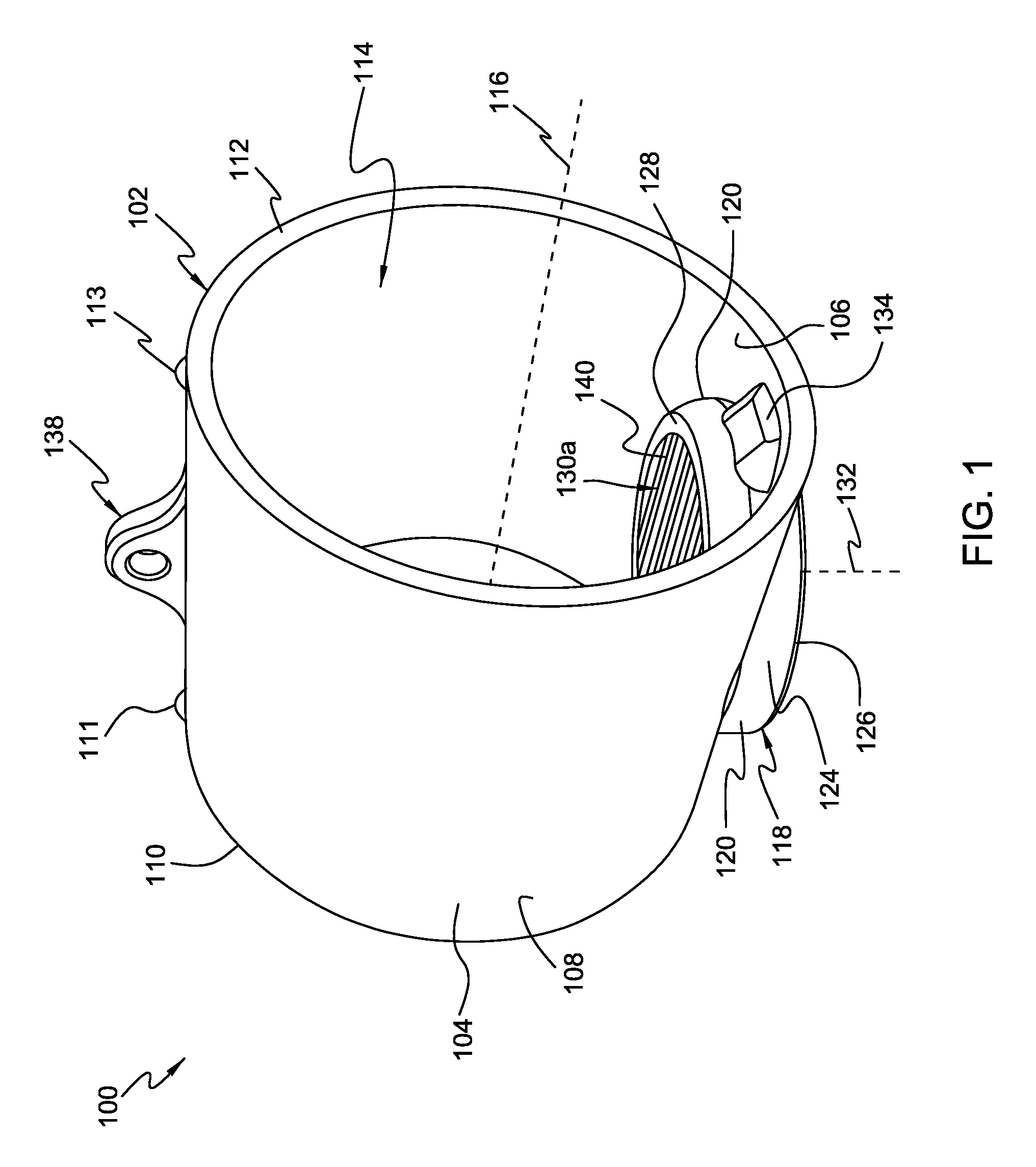
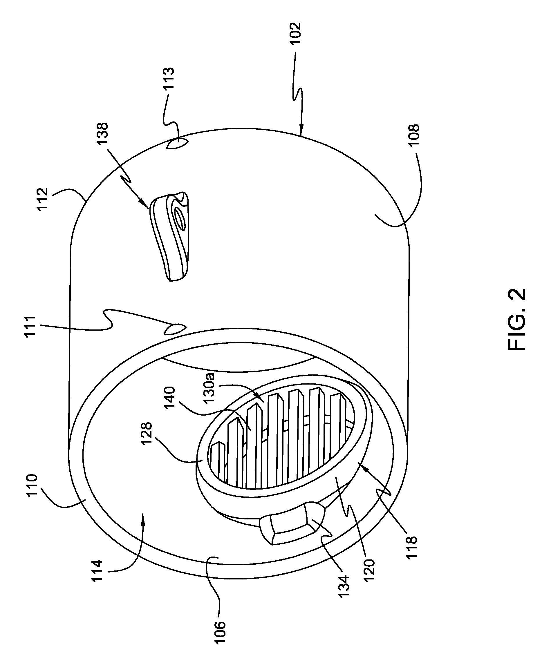
[0032]FIGS. 1-7 present various views of an airflow treatment device 100 that is configured to treat air in an air handling system. As will be discussed in more detail herein, the airflow treatment apparatus or device 100 is configured to be installed inline in the ductwork of an air handling system (e.g., HVAC system) in a manner that is substantially free of obstructing the airflow through the ductwork or requiring any supplemental power to treat the airflow passing by the treatment device. The disclosed airflow treatment device can also be maintained substantially free of any interruptions, disassembly or downtime to the air handling system after initial inline installation of the disclosed airflow treatment device 100.

[0033]Broadly, the device 100 includes a first body 102 having a first wall 104 with opposite inner and outer surfaces 106, 108 and opposite first and second open free ends 110, 112. The first wall 104 defines an airflow passageway 114 through the device 100 that e...


PUM

PropertyMeasurementUnit
anglesaaaaaaaaaa
anglesaaaaaaaaaa
anglesaaaaaaaaaa

Abstract

An airflow treatment device configured to be installed inline in the ductwork of an air handling system (e.g., HVAC system) in a manner that is substantially free of obstructing the airflow through the ductwork or requiring any supplemental power to treat the airflow passing by the treatment device. The disclosed airflow treatment device can also be maintained substantially free of any interruptions, disassembly or downtime to the air handling system after initial inline installation of the disclosed device. In one arrangement, the airflow treatment device is capable of accepting a threaded odor neutralizer container at its base. Ductwork need only be disassembled once to attach the disclosed device inline in the airflow path of the ductwork. When the odor neutralizing agent needs replenished, the container can be detached from the device, replenished, and reattached to the device free of disruption to the air flow of the air handling system.

Description

CROSS REFERENCE TO RELATED APPLICATION[0001]This application claims priority to U.S. Patent App. No. 62 / 011,375, entitled “INLINE APPARATUS CAPABLE OF ACCEPTING A THREADED CONNECTION AT ITS BASE,” and filed on Jun. 12, 2014, the entire contents of which are incorporated herein in their entirety as if set forth in full.BACKGROUND OF THE INVENTION[0002]1. Field of the Invention[0003]This invention relates to the field of heating, ventilating and air conditioning (HVAC) systems and, more particularly, to devices that treat airflow through the ductwork, hoses or the like of HVAC systems.[0004]2. Description of Related Art[0005]It is common to employ one or more devices in homes, buildings, and other enclosed spaces to treat the air being inhaled by inhabitants in various manners. As one example, various types of odor management (e.g., neutralizing or elimination) systems have been utilized in which an air flow is moved past a product which may be vaporized, either by evaporation or subl...

Claims


Application Information

Patent Timeline
Patent Type & Authority Patents(United States)
IPC IPC(8): A61L9/12A61L9/013F24F3/16F24F8/50
CPCA61L9/12A61L9/013A61L9/122A61L2209/16Y10T29/49828Y10T137/4891F24F8/50A61L2209/15F24F13/0209
Inventor EIKE, MASON EDWARD
Owner EIKE MASON EDWARD
Why Eureka
Try Eureka