

Reactor-condenser for the synthesis of urea
a technology of urea and condenser, which is applied in the direction of organic chemistry, chemical/physical/physical-chemical processes, products, etc., can solve the problems of coils reducing the available internal volume, difficult inspection with the usual non-destructive techniques, and cost sources, etc., to achieve efficient and cost-effective layout
Active Publication Date: 2019-12-03
CASALE SA
View PDF4 Cites 0 Cited by
- Summary
- Abstract
- Description
- Claims
- Application Information
AI Technical Summary
Benefits of technology
This design enhances heat and mass transfer, increases conversion yield, and reduces costs by eliminating the need for internal coils and complex elevations, while integrating condensation and synthesis in a single, efficient equipment setup.
Problems solved by technology
This reactor however necessitates heat exchange coils to remove heat from the first reaction zone and to furnish heat to the second reaction zone, which are a source of cost since the coils are exposed to an aggressive environment and must be made of an expensive material, e.g. high alloyed steel.
Furthermore, the coils reduce the available internal volume and they are very difficult to inspect with the usual non-destructive techniques.
In order to provide a static head enough to ensure a stable circulation flow, the equipment must be positioned at different heights leading to a layout which is significantly developed in elevation, typically up to 60 meters, and consequently is expensive.
For example the reactor is installed above the stripper requiring an expensive supporting structure.
Hence the modern 002-stripping technology still has the drawback of requiring a structure which has an important impact on the global investment cost.
Method used
View moreImage
Smart ImageViewing Examples

Examples
second embodiment
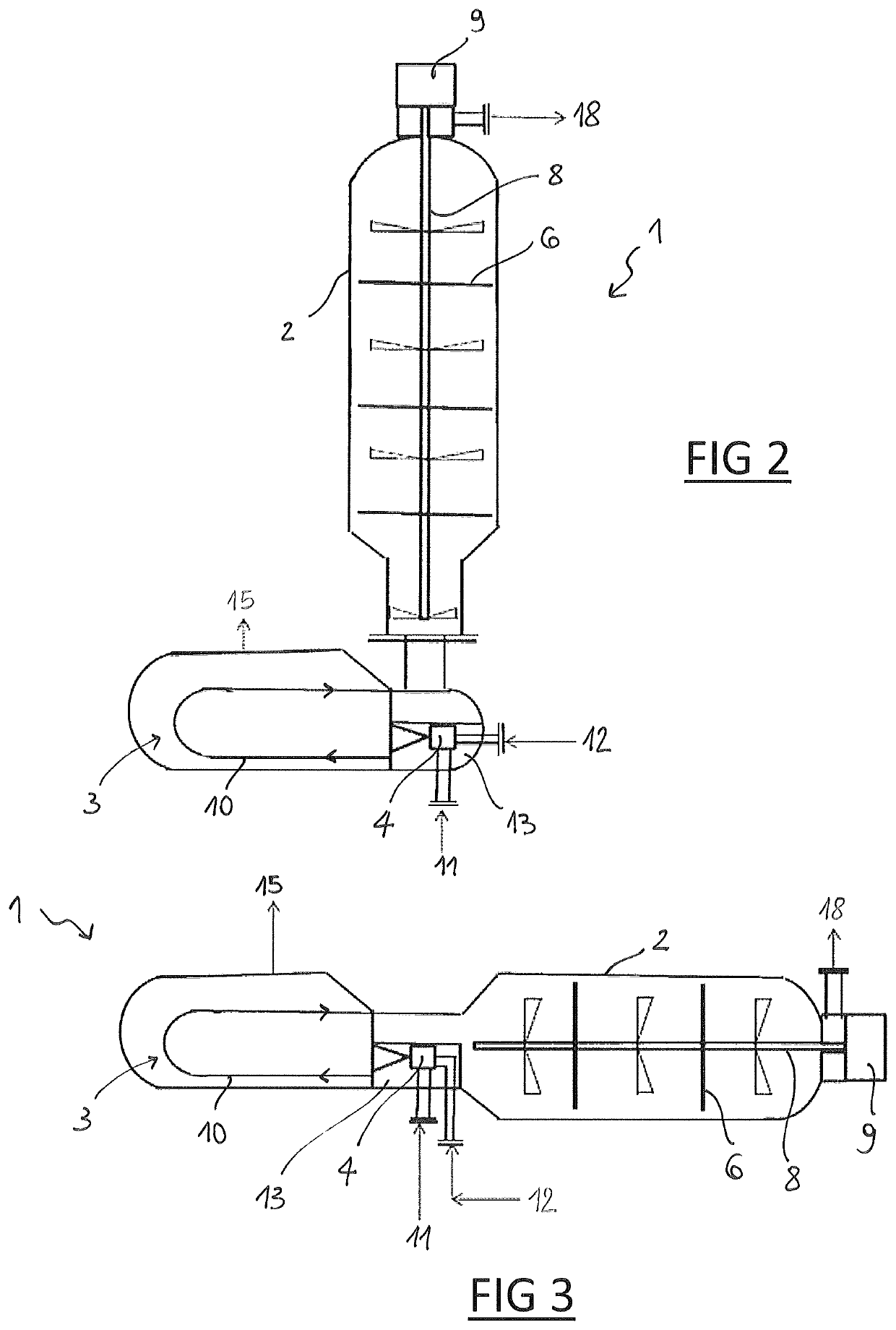
[0044]FIG. 2 shows a second embodiment where the condensation section 3 is horizontally arranged. In this embodiment the ejector 4 is located inside the vessel of the condensation section, in the feeding partition 13.
third embodiment
[0045]FIG. 3 shows a third embodiment having a horizontal layout of both the reaction section 2 and condensation section 3. In this embodiment the drive impeller 7A can be omitted as the flow through the reactor does not have to overcome the height of the reaction section.
[0046]The combined reactor of the invention can be inserted in a urea synthesis loop, for example by connection with a stripper. Hence the invention is useful to new urea plants and also to the revamping of existing plants.
Login to View More PUM
| Property | Measurement | Unit |
|---|---|---|
| pressure | aaaaa | aaaaa |
| heights | aaaaa | aaaaa |
| temperature | aaaaa | aaaaa |
Abstract
A combined reactor and condenser for the synthesis of urea from ammonia and carbon dioxide, including a condenser section coupled to a reaction section, comprising inputs directed to said condenser section for a gaseous stream comprising ammonia and carbon dioxide and for a solution containing ammonium carbamate and liquid ammonia, and wherein the effluent of the condenser section is sent to the reaction section; the reaction section comprises a plurality of compartments and a plurality of mixers, at least one inside each of said compartments.
Description
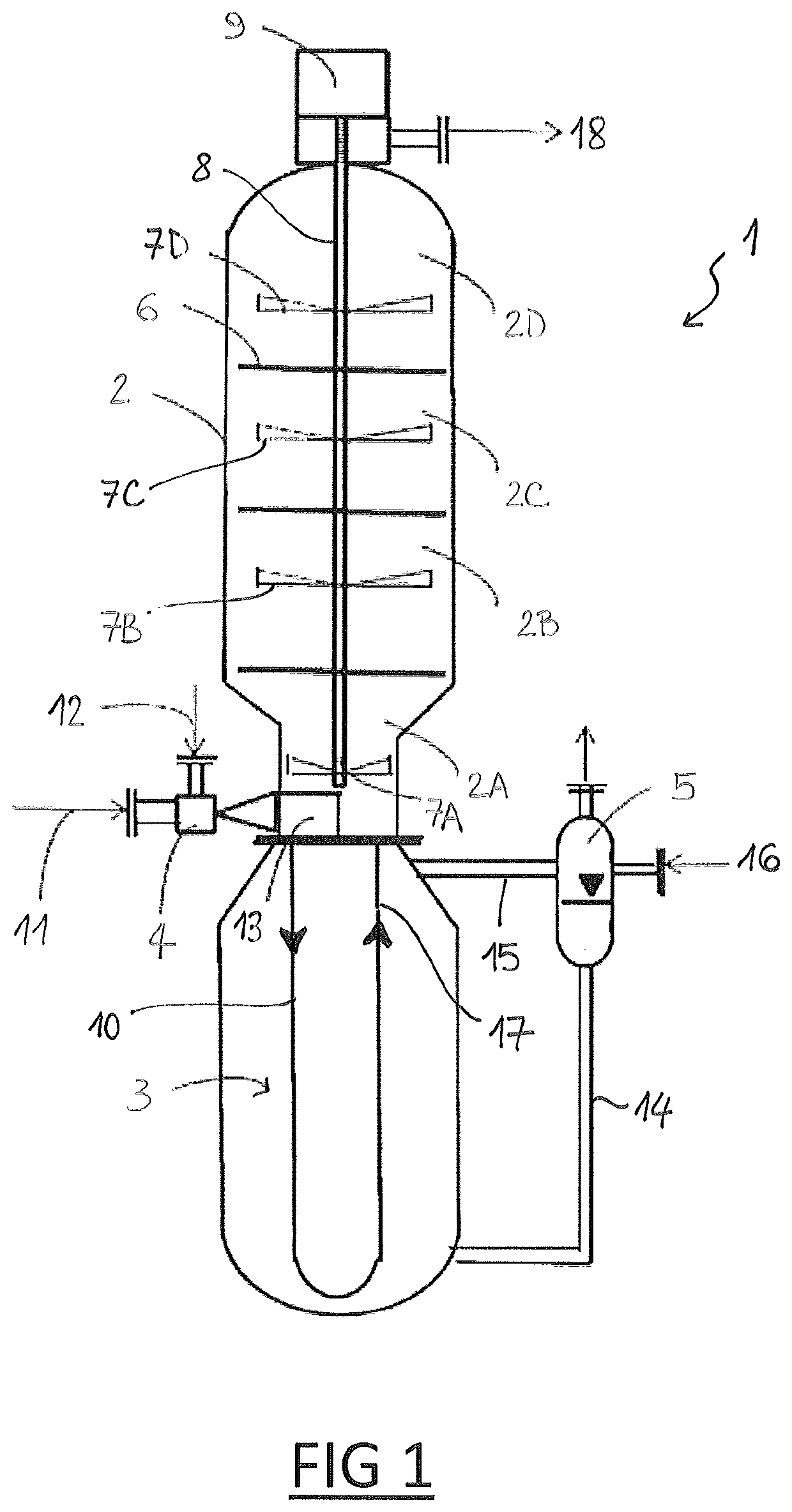
[0001]This application is a national phase of PCT / EP2016 / 067301, filed Jul. 20, 2016, and claims priority to EP 15182263.2, filed Aug. 25, 2015, the entire contents of both of which are hereby incorporated by reference.FIELD OF THE INVENTION[0002]The invention relates to the field of equipment for the synthesis of urea. The invention relates in particular to a combined reactor-condenser for the synthesis of urea.Prior Art[0003]Urea is commonly synthesized by reaction of ammonia with carbon dioxide, which involves a fast and highly exothermic step of formation of ammonium carbamate, and a slightly endothermic step of conversion of ammonium carbamate into urea and water.[0004]The reactive system is a vapour-liquid heterogeneous system, where the reactants are progressively transferred from the vapour phase to the liquid phase. It is well accepted that the heat and mass transfer of reactants among the phases are of crucial importance in determining the conversion rate.[0005]The synthes...
Claims
Login to View More Application Information
Patent Timeline
 Patent Type & AuthorityPatents(United States)
IPC IPC(8): B01J19/18B01J19/00B01J19/20C07C273/04
CPCB01J19/1812B01J19/0066B01J19/20C07C273/04B01J2219/00076B01J2219/00768B01J2219/00777B01J2219/00779B01J2219/182B01J2219/185Y02P20/142Y02P20/141
InventorRUGNONE, LUCA
OwnerCASALE SA