Method for producing steel pipe plated with metal by thermal spraying

a technology of thermal spraying and steel pipes, which is applied in the direction of superimposed coating process, manufacturing tools, soldering apparatus, etc., can solve the problems of difficult to form thermal spraying metal layers in uniform manner, difficult to finely control the thickness of thermal spraying metal layers, and difficult to ensure the corrosion resistance of steel tubes. , to achieve the effect of excellent corrosion resistance and effective rust prevention

Active Publication Date: 2012-06-28
DAIWA STEEL TUBE IND
View PDF2 Cites 0 Cited by
  • Summary
  • Abstract
  • Description
  • Claims
  • Application Information

AI Technical Summary

Benefits of technology

[0009]Proposed in the light of the above, the present invention has an object of providing a process for producing a thermal sprayed, metal plated steel tube having a substantially uniform and favorable metal layer over the whole surface in a highly productive manner. The present invention has another object of forming a metal layer having sufficient bonding strength with a metal layer of a plated layer.
[0020]According to the present invention, a metal layer is formed over the internal or external surface of a metal tube by thermal spraying, instead of a conventional plating step, such as molten plating, with a result that highly expensive installation and maintenance of plated layers may be dispensed with, a wide variety of metal layers may be formed with low-cost initial investment and the degree of freedom for designing metal tubes may be increased.
[0022]According to the present invention, a thermal sprayed, metal plated steel tube that is excellent in corrosion resistance and effective in rust prevention may be obtained by forming an aluminum layer and an alloy metal containing aluminum in zinc plating using a thermal spraying device.

Problems solved by technology

Since bonding strength of thermal sprayed metal layers at the interface with the steel tubes is poorer in comparison with that of molten plated layers, when a processing such as bending is applied, the thermal sprayed metal layers will develop delamination and / or cracking, potentially causing problems in corrosion resistance of the steel tubes.
Also, it is difficult to finely control the thickness of the thermal sprayed metal layers, making it difficult to form thermal sprayed metal layers in a uniform manner.

Method used


Image

  • Method for producing steel pipe plated with metal by thermal spraying
  • Method for producing steel pipe plated with metal by thermal spraying
  • Method for producing steel pipe plated with metal by thermal spraying

Examples


example 1

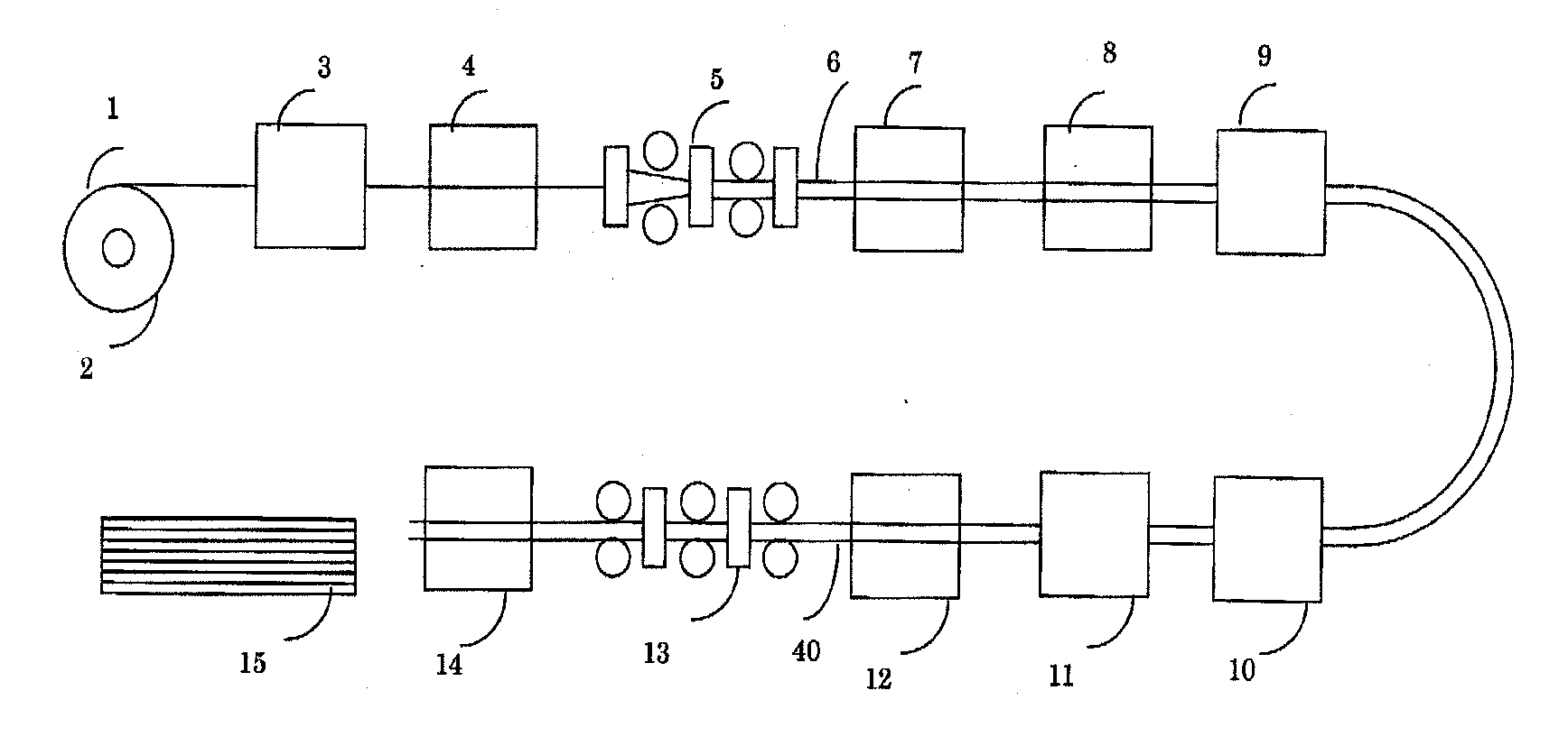
[0055]Aluminum was used as a metal to be thermal sprayed. A rolled continuous steel plate with a thickness of 1.2 mm and a width of 59.5 mm was set in a production line as shown in FIG. 1 and was processed with shot blasting on the internal surface with a shotblast, followed by being applied with a thermal sprayed metal layer over the internal surface with a thermal spraying device. In addition, after a molten zinc plating device, aluminum was thermal sprayed with an external surface thermal spraying device.

[0056]According to the present invention, conditions such as temperatures of the surface of zinc at the time of thermal spraying (ordinary temperature to 450° C.), line speeds (0 to 400 m / min) and spraying angles (0 to 90°) can be combined as appropriate. Concurrently, the bonding concentrations and distribution of aluminum can be controlled by adjustment of the amounts of thermal sprayed aluminum.

[0057]FIG. 5 shows in comparison appearances of a steel tube produced by Example 1 ...

example 2

[0061]Aluminum was used as a metal to be thermal sprayed, and a rolled continuous steel plate with a thickness of 1.2 mm and a width of 59.5 mm was set in a production line as shown in FIG. 1 and was processed with shot blasting on the internal surface with a shotblast device, followed by being applied with a thermal sprayed metal layer over the internal surface with a thermal spraying device. In addition, after molten zinc plating, aluminum was thermal sprayed with an external surface thermal spraying device.

[0062]A photograph of the appearance of the obtained section is shown in FIG. 6 (a) and the elemental analysis of the section as determined by EPMA is shown in the chart of FIG. 6 (b). As shown in FIG. 6 (a), characteristic scattering of the thermal sprayed metal in the shape of tiny islands throughout the substrate metal is observed also in this example. It is seen that tiny dots of blackish aluminum are scattered throughout the whitish zinc substrate. In addition, as shown in...

example 3

[0063]Aluminum was used as a metal to be thermal sprayed, and a rolled continuous steel plate with a thickness of 1.2 mm and a width of 59.5 mm was set in a production line as shown in FIG. 1 and was processed with shot blasting on the internal surface with a shotblast, followed by being applied with a thermal sprayed metal layer over the internal surface with a thermal spraying device. In addition, after a molten zinc plating device, aluminum was thermal sprayed with an external surface thermal spraying device. In this example, aluminum was thermal sprayed at 15 g / min with a surface temperature of the zinc plating of 400° C. during a low production rate of 20 m / min with a spraying angle of 90°. Contact between the zinc and the thermal sprayed aluminum fuses to promote bonding with the aluminum so that distribution of an aluminum layer at the surface, a zinc-aluminum layer in-between and a zinc layer at the innermost layer may be obtained. This arrangement is feasible at a medium to...


PUM

PropertyMeasurementUnit
melting pointaaaaaaaaaa
temperatureaaaaaaaaaa
widthaaaaaaaaaa

Abstract

To provide a process for producing a thermal sprayed, metal plated steel tube having a metal layer substantially uniform and favorable over the whole surface in a highly productive manner.[Means for solving] A process for producing a metal tube comprising continuously forming a metal plate composed of a first component into a tubular shape and continuously welding its butted ends to form the metal tube, wherein, after the continuous welding, a metal layer composed of a second component which is different from the first component is formed by thermal spraying directly over the surface of the metal tube, the metal layer having no discontinuities in the circumferential and lengthwise directions. Especially it is preferred that the process comprises a process step of making the thickness distribution of the metal layer more uniform after formation of the thermal sprayed metal layer over the external surface.

Description

[0001]The present application is a divisional application of copending U.S. application Ser. No. 11 / 791,052, filed Jun. 27, 2007, which is the U.S. National Stage of International Application No. PCT / JP2004 / 017202, filed Nov. 18, 2004. The disclosures of these applications are incorporated herein by reference.BACKGROUND OF THE INVENTION[0002]The present invention relates to a process for producing a metal plated steel tube, comprising a thermal spraying step to the internal or external surface of the steel tube.[0003]Traditionally, processes for producing metal plated steel tubes are known which comprise a step of continuously forming a steel plate that is plated on both sides with a heterogeneous metal (typically, zinc) into a tubular shape using roll forming, a step of continuously welding the tubular plated steel plate so formed at its end faces to form a tube, a step of continuously cutting weld beads that are formed on the external surface of the steel tube during the previous ...

Claims


Application Information

Patent Timeline
Patent Type & Authority Applications(United States)
IPC IPC(8): B23K31/02
CPCC23C4/02C23C4/08C23C4/16C23C30/00Y10T428/12292C23C28/00C23C28/021C23C28/023C23C28/025C23C28/028
Inventor NAKAMURA, SHINICHIROTAMAMURA, TADAYOSHI
Owner DAIWA STEEL TUBE IND
Why Eureka
Try Eureka