Method and device for operating a trigger device for occupant protection means

a technology for occupant protection and trigger devices, which is applied in the direction of pedestrian/occupant safety arrangements, vehicle components, instruments, etc., can solve the problems of irreparable damage of the trigger device, and achieve the effects of saving valuable energy, saving space, and saving energy

Active Publication Date: 2017-01-10
ROBERT BOSCH GMBH
View PDF19 Cites 4 Cited by
  • Summary
  • Abstract
  • Description
  • Claims
  • Application Information

AI Technical Summary

Benefits of technology

[0013]The advantage of the presented method according to the present invention is that, as a result, an activation of occupant protection means is possible even in the event of a short circuit to the supply voltage. By detecting an output voltage at the second switch, it is possible to recognize from the progression of the detected voltage after activation of the second switch that a short circuit to the supply voltage is now present, which in the event of a longer activation of the second switch may result in the trigger device becoming irreparably damaged.
[0032]In one advantageous embodiment of the device according to the present invention, the device has means for detecting time periods, the means for detecting time periods in particular being designed in such a way that the means detect time periods which differ by at least one power of ten. As a result of the use of such means, it is advantageously achieved that the device is able to deactivate the second switch after the shortest possible time in the event of a short circuit. In the event of a short circuit according to Case B, it is absolutely necessary to prevent further current flow through the trigger means as quickly as possible, to thereby prevent a high thermal load and possible destruction of the trigger means.

Problems solved by technology

By detecting an output voltage at the second switch, it is possible to recognize from the progression of the detected voltage after activation of the second switch that a short circuit to the supply voltage is now present, which in the event of a longer activation of the second switch may result in the trigger device becoming irreparably damaged.

Method used


Image

  • Method and device for operating a trigger device for occupant protection means
  • Method and device for operating a trigger device for occupant protection means
  • Method and device for operating a trigger device for occupant protection means

Examples


Embodiment Construction

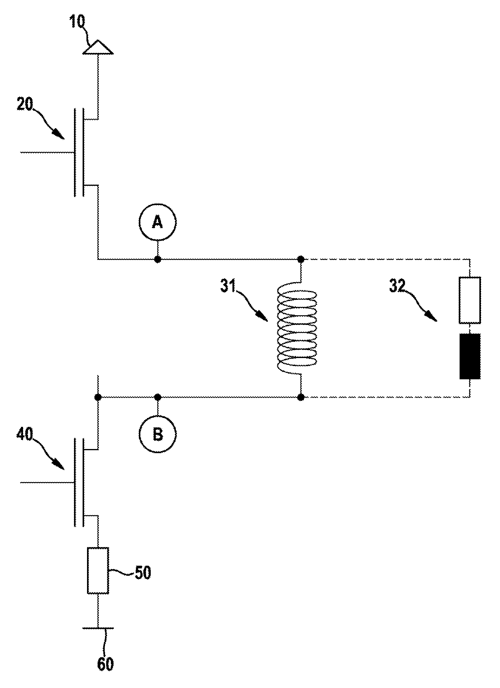
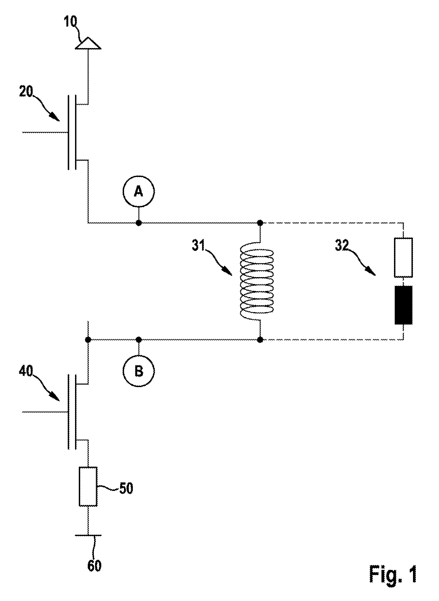
[0038]FIG. 1 shows a circuit diagram of a trigger device according to one specific embodiment of the present invention. Reference numeral 10 denotes a supply voltage, reference numeral 20 denotes a first switch or a high side switch, reference numeral 31 denotes a pyrotechnic trigger means, reference numeral 32 denotes an inductive trigger means, reference numeral 40 denotes a second switch or a low side switch, reference numeral 50 denotes a (forward slope) resistance RDSon, and reference numeral 60 denotes a ground potential.

[0039]Points A and B indicate locations at which a short circuit to a supply voltage 10 may occur. When a short circuit occurs at point A, it is referred to as a short circuit on high side switch 20. If the short circuit is present with low resistance, it involves a short circuit of Case A. When a short circuit occurs at point B, it is referred to as a short circuit on low side switch 40. If the short circuit is present with low resistance, it involves a short...


PUM


Abstract

A method for operating a trigger device for an occupant protection unit includes: activating a first switch (high side) of the trigger device for occupant protection units; activating a second switch (low side) of the trigger device for occupant protection units; detecting an output voltage at the second switch (low side); and deactivating the second switch (low side) as a function of the output voltage.

Description

BACKGROUND OF THE INVENTION[0001]1. Field of the Invention[0002]The present invention relates to a method for operating a trigger device for occupant protection means, to a device for triggering occupant protection means, and to a control unit.[0003]2. Description of the Related Art[0004]A number of methods for operating a trigger device for occupant protection means are already known from the related art, in which at least two switches, so-called output stages, are activated for triggering purposes to connect at least one trigger means to a voltage supply.[0005]Trigger devices for occupant protection means are generally electrical or electronic components. Trigger devices additionally come into play whenever high physical forces act on a vehicle, for example in the instance of a collision. For a wide variety of reasons, there is the possibility that a short circuit forms in the ignition circuit.[0006]In today's trigger devices for occupant protection means, the output stages are al...

Claims


Application Information

Patent Timeline
Patent Type & Authority Patents(United States)
IPC IPC(8): G05F1/00B60R21/017B60R21/01
CPCB60R21/017B60R21/0173B60R2021/01143B60R2021/01252
Inventor BALZ, STEFAN
Owner ROBERT BOSCH GMBH
Why Eureka
Try Eureka