[0007]Therefore, it is the task of this invention to create a hydro bushing in a way so that its load on the material, in the area of the link between the cavity walls and the bushing body, in the case of large radial forces overlaid by strong torque forces, will be reduced and, at the same time, improving the permanent durability of the bars.
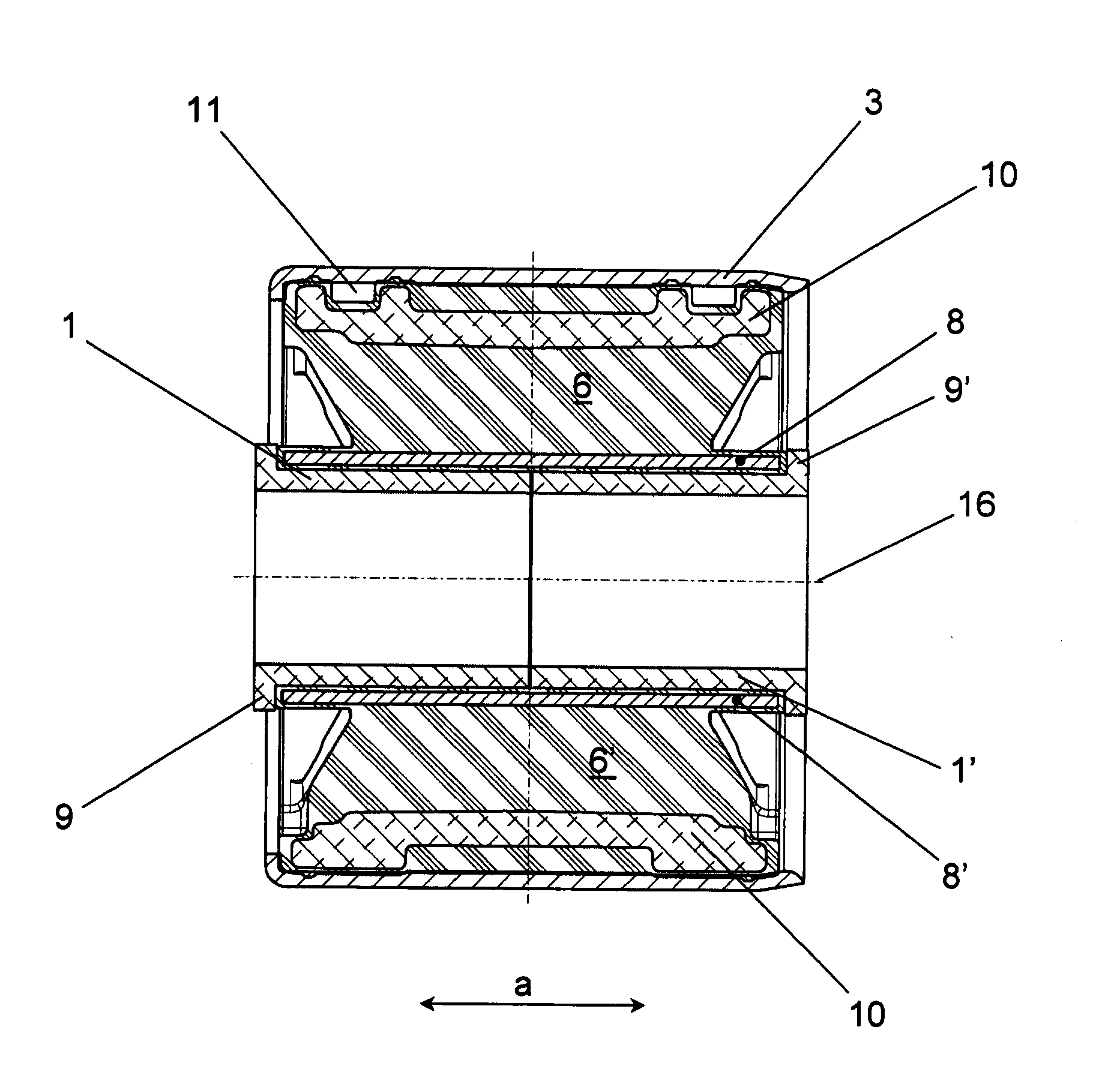
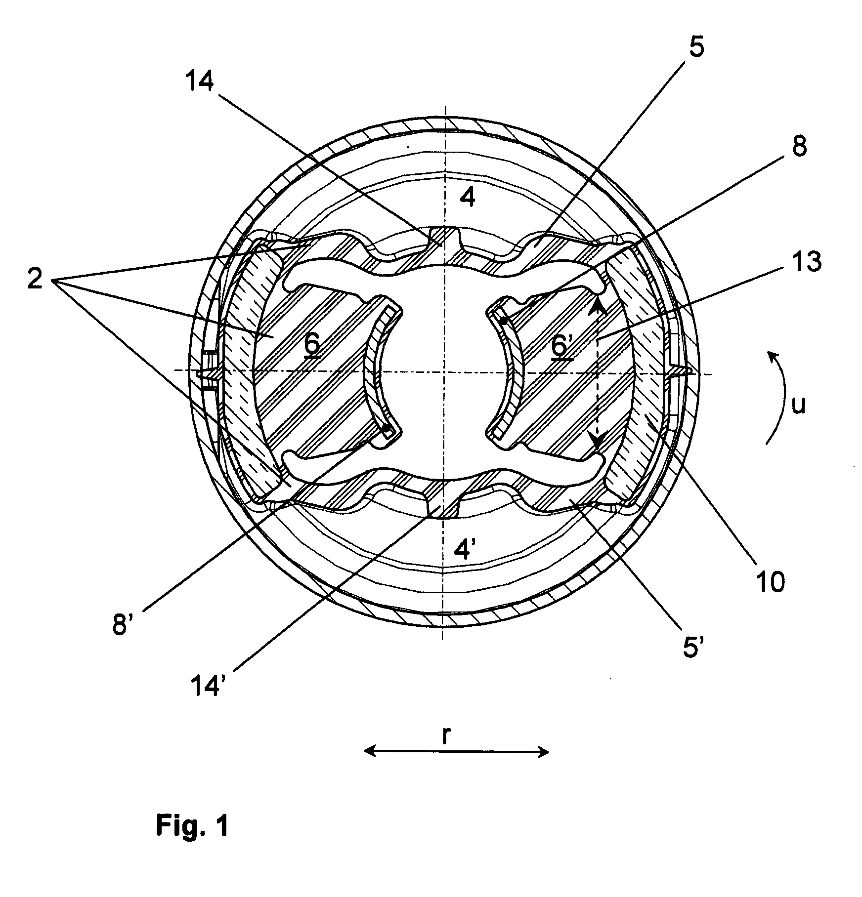
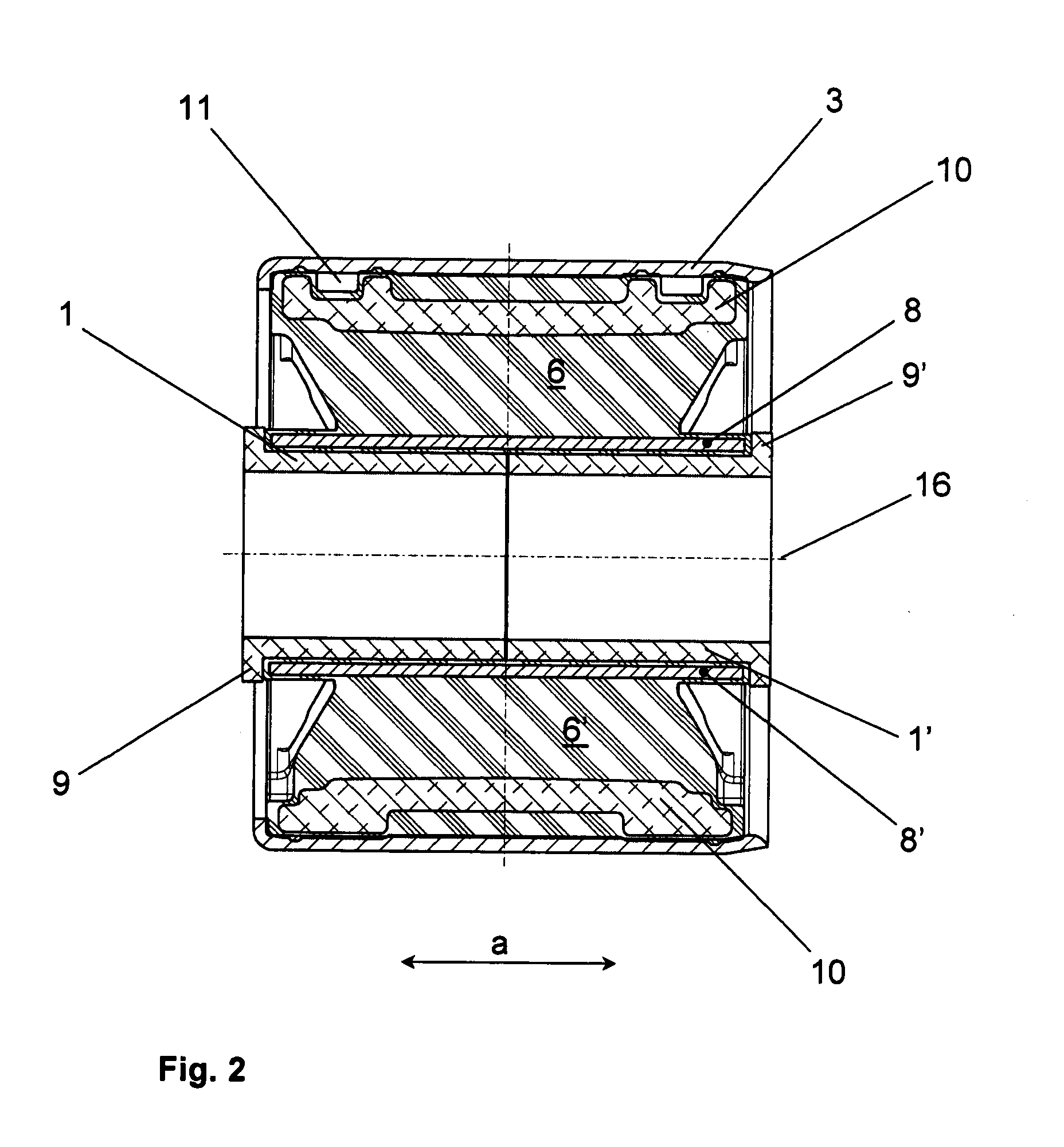
[0009]To achieve additional improvements for permanent durability in the area of the bars, the invented bushing is designed in a way so that its outer sleeve and bushing body, linked via
vulcanization with the outer sleeve, including the bars and its connected swell walls in the radial outer area form a separate part. The inner part is inserted, in accordance with the invention, into this separate part designed as rubber-
metal-part. The inner part has a larger boundary, in comparison to the rubber-
metal-part inner absorbing geometry. In addition, the axial ends of the inner part are designed to have overhangs, directed radial to the outside. These overhangs, after the
insertion of the inner part into the rubber-metal-part, formed by the holder sleeve and the bushing body, are engaged by bar plates from behind, which are vulcanized into the bars and lie inside. Hereby, via its vulcanized bar plates with a pre-load, the bars are provided in an advantageous way, based on the already mentioned larger boundary of the inner part, thereby improving the permanent durability. In regard to the passage, which connects the swell cavities with each other, a passage carrier part is preferably vulcanized into the radial outer area of the bushing body, meaning in the area of the link of the swell walls to the cavities, bordering the bar. This passage carrier part forms a protection, at the same time, for the bushing body.
[0012]Beside the passage, which serves to connect the swell cavities and therefore as support for the damping effect, that bushing can also be equipped with a short passage functioning as a bypass for the first mentioned passage, whereby the particular bypass passage, under normal operation of the bushing, is blocked via an inner blocking part and which opens briefly only when high radial loads occur. Basically, such a bypass passage can be waived in the proposed bushing configuration, since brief, high loads can be compensated by the flexibility of the free hanging swell wall. For special applications, however, a bypass passage can still be provided, whereby it can be dimensioned, or the blocking part in it, that high loads result with a flexibility, step-by-step, first through the free hanging swell wall and followed by releasing the bypass passage. For coordination or adjustment, respectively, of the radial stiffness behavior of the bars, these bars can have additional bar plates vulcanized into them. The invented bushing is advantageously constructed by the design of the bars, in the area of connecting the cavity walls with regard to the circumferential direction, are smaller, meaning that they are tailor shaped. Hereby, the permanent duration of the bushing, in the area of connecting the swell walls, also has been improved.
[0013]In an advantageous construction of the invented bushing, a radial shaping of the bushing body, rising to the outside, is provided and located in a bottom section of the cavities, meaning in a preferably axial centered inner area. The positioning of such nipples or pimples, respectively, serves to simplify mounting, especially
insertion of the inner part into the rubber-metal-part. It is hereby possible to pull, temporarily and during
assembly, the bottom section of the cavities, meaning the respective area of their swell walls by means of the nipples, to the outside for making the
insertion of the inner part easier.

