Thermal Ratchet System

Inactive Publication Date: 2013-04-25
SCHLUMBERGER TECH CORP
View PDF5 Cites 5 Cited by
  • Summary
  • Abstract
  • Description
  • Claims
  • Application Information

AI Technical Summary

Benefits of technology

[0005]Certain embodiments provide significant advantages, including, for example, providing a way to main

Problems solved by technology

Mechanical equipment is often subjected to considerable mechanical stress when operated in environments wherein temperatures are cyclic.
Mechanically coupling components made from materials exhibiting different coefficients of thermal expansion can cause many such components to fail.
These disparate changes in dimension can be particularly damaging when the changes are repeated over a period of time.
Seals, such as those utilized in downh

Method used


Image

  • Thermal Ratchet System
  • Thermal Ratchet System
  • Thermal Ratchet System

Examples


Example

[0016]While the invention is susceptible to various modifications and alternative forms, specific embodiments thereof have been shown by way of example in the drawings and are herein described in detail. It should be understood, however, that the description herein of specific embodiments is not intended to limit the invention to the particular forms disclosed, but on the contrary, the intention is to cover all modifications, equivalents, and alternatives falling within the scope of the invention as defined by the appended claims.

DETAILED DESCRIPTION

[0017]Illustrative embodiments of the invention are described below. In the interest of clarity, not all features of an actual implementation are described in this specification. It will of course be appreciated that in the development of any such actual embodiment, numerous implementation-specific decisions must be made to achieve the developer's specific goals, such as compliance with system-related and business-related constraints, wh...


PUM


Abstract

A thermal ratchet system includes a ratchet housing, a ratchet mandrel, a first ratchet, and a second ratchet. The first ratchet is disposed at a position generally fixed with respect to the ratchet housing and is urgeable with respect to the ratchet mandrel in an axial direction by a change in environmental temperature in a first direction. The second ratchet is disposed at a position generally fixed with respect to the ratchet housing and is urgeable with respect to the ratchet mandrel in the axial direction by a change in environmental temperature in a second direction opposite to the first direction. At least one of the first ratchet and the second ratchet is engaged with the ratchet mandrel.

Description

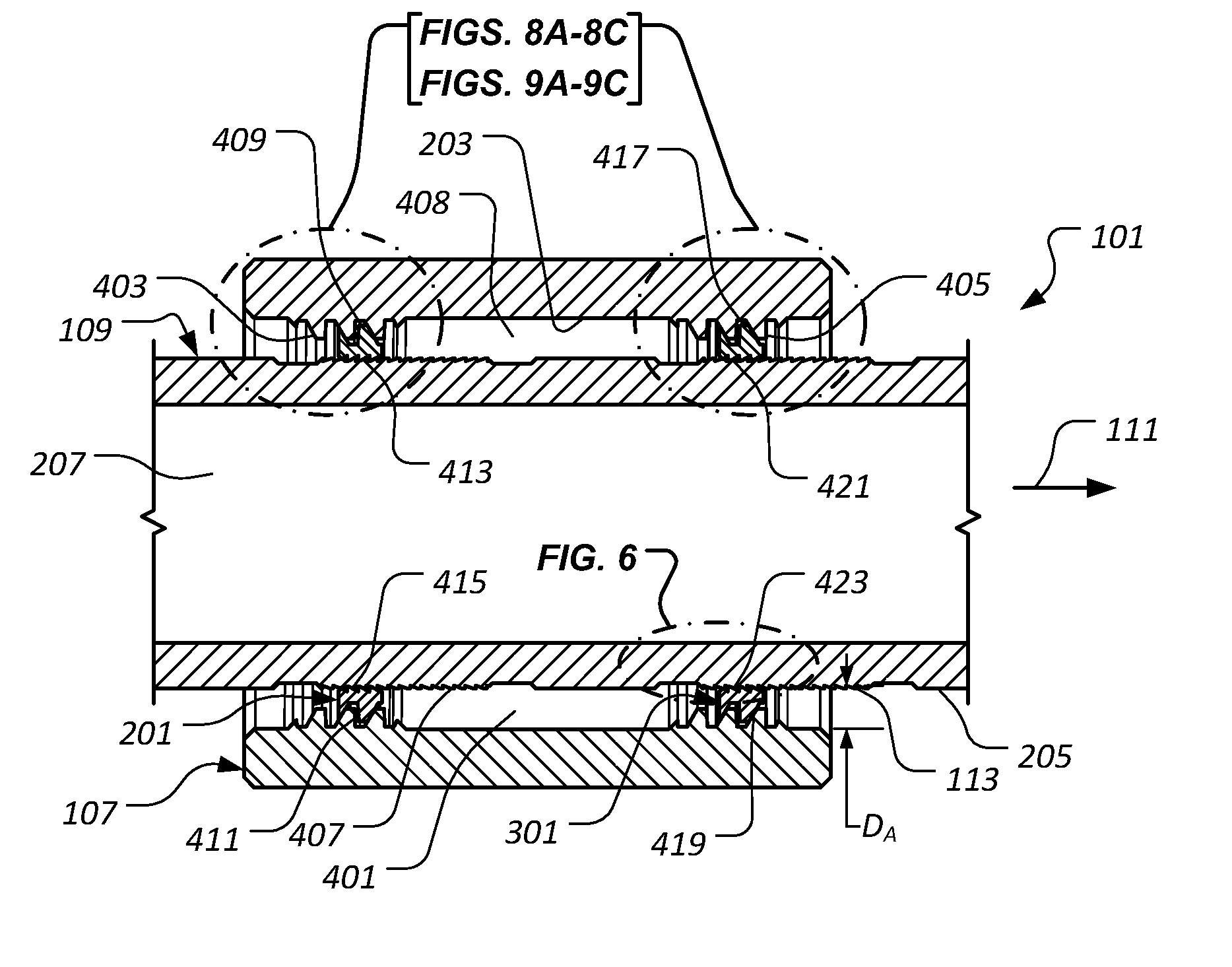
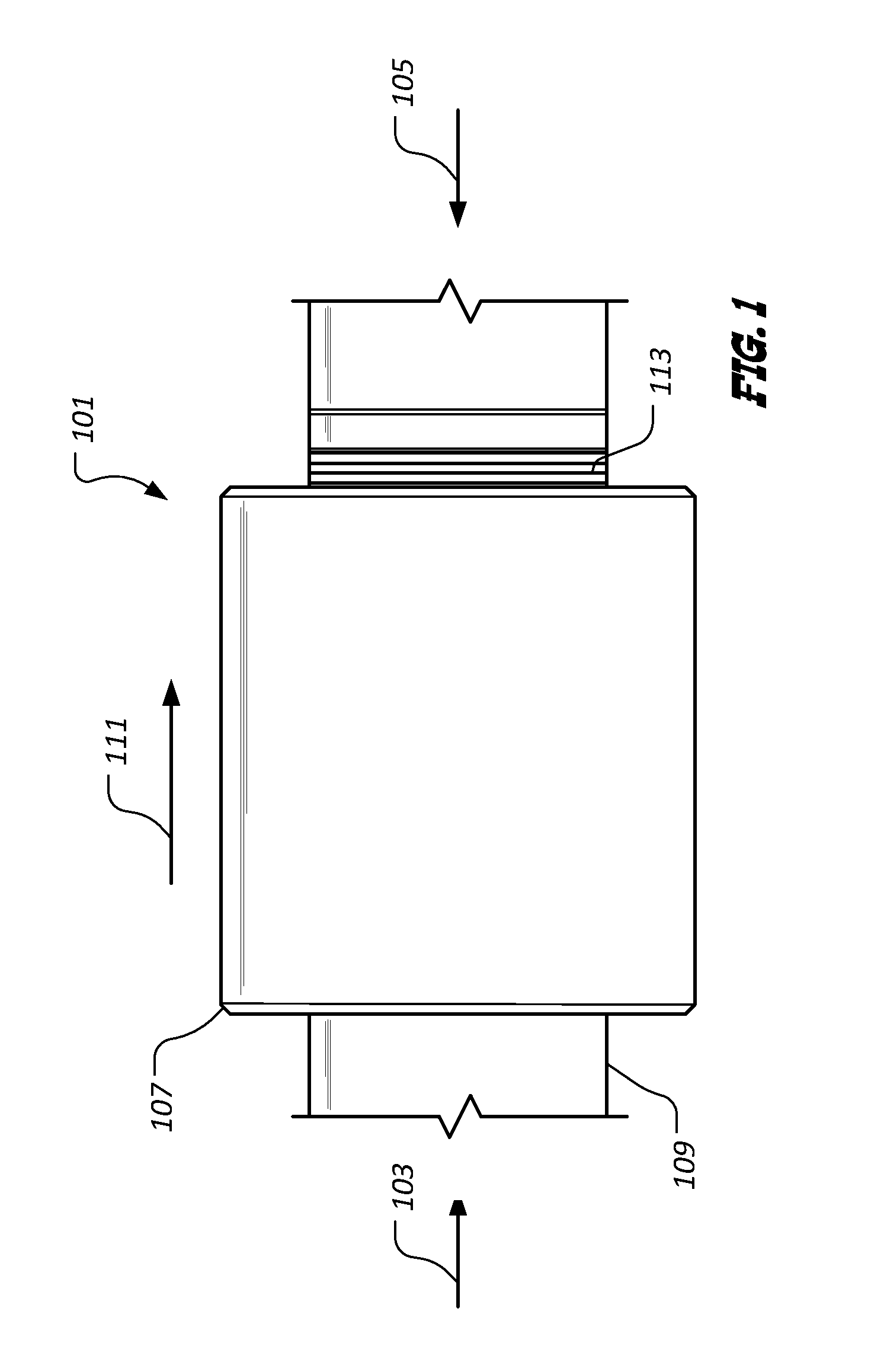
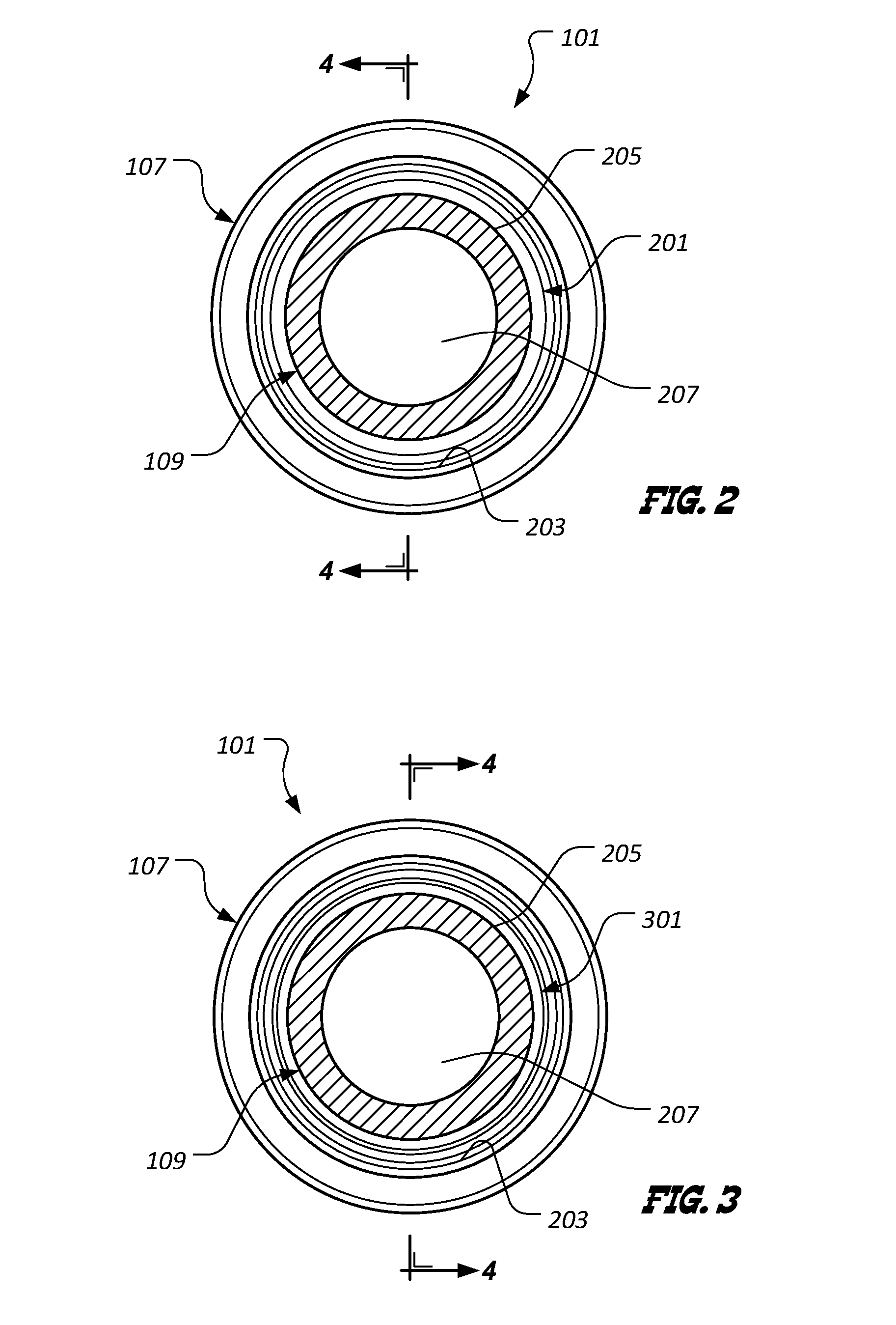
BACKGROUND[0001]Mechanical equipment is often subjected to considerable mechanical stress when operated in environments wherein temperatures are cyclic. In such environments, for example, components that are made from materials that exhibit larger coefficients of thermal expansion change dimensions as a result of temperature fluctuations to a greater degree than other components that are formed from materials exhibiting smaller thermal expansion coefficients. Mechanically coupling components made from materials exhibiting different coefficients of thermal expansion can cause many such components to fail. These disparate changes in dimension can be particularly damaging when the changes are repeated over a period of time.[0002]Seals, such as those utilized in downhole oilfield operations, for example, are particularly susceptible to failure when operated in environments wherein temperatures are cyclic. Components often referred to as “energizers” are used to bias seals against sealin...

Claims


Application Information

Patent Timeline
IPC IPC(8): F03G7/06F16H27/02
CPCF03G7/06Y10T74/1535Y10T74/2141F16H19/043F16H27/02F16H31/005
Inventor STRETCH, MITCHEL
Owner SCHLUMBERGER TECH CORP
Why Eureka
Try Eureka