
Process for encapsulating soluble biologics, therapeutics, and imaging agents

Active Publication Date: 2019-01-10
THE TRUSTEES FOR PRINCETON UNIV
View PDF0 Cites 6 Cited by
  • Summary
  • Abstract
  • Description
  • Claims
  • Application Information

AI Technical Summary

Benefits of technology

The invention is a process for making microparticles that overcomes limitations of current processes. This process involves a gradual precipitation of the soluble agent, resulting in higher loadings of up to 75 wt % solids, and controlled release kinetics. Compared to previous processes, the invention allows for more precise control over release rates and allows for microparticle formation with no added matrix or a minor amount of matrix material. The process also allows for fine dispersions of the biologic throughout the microparticle. These features make this process more efficient and effective for controlled release applications.

Problems solved by technology

This specificity comes as a result of structural complexity, which is a strength of biologics for use as therapeutics and a challenge in trying to formulate and deliver them (S. Mitragotri, P. A. Burke, R. Langer, Overcoming the challenges in administering biopharmaceuticals: formulation and delivery strategies, Nat Rev Drug Discov.
While there have been recent promising advances in oral delivery of biologics, the difficulty in translocating NPs through mucus layers and across the GI (gastrointestinal) tract epithelial layer makes this a less developed area than parenteral administration.
The lack of control in the emulsion step and the fact that the internal soluble drop is a fluid has limited loadings that can be achieved and controlled release kinetics to microparticles with loadings generally less than 10 wt % solids.
The lack of uniformity of those coatings, again, compromises release control at high agent loadings.
The combination of high loading, lack of burst release, and controlled release in microparticles from 1 micron to 1 mm or 2 mm constructs has not been possible previously.
These approaches fail because the dry agent powders cannot be commuted down to nanoparticle size.
Therefore, in the emulsion step with these powders to make microparticles, particle contacts cause percolation and lack of controlled release when formulations of high active loading are attempted.

Method used


Image

  • Process for encapsulating soluble biologics, therapeutics, and imaging agents
  • Process for encapsulating soluble biologics, therapeutics, and imaging agents
  • Process for encapsulating soluble biologics, therapeutics, and imaging agents

Examples


example 1

Assembly and Morphology

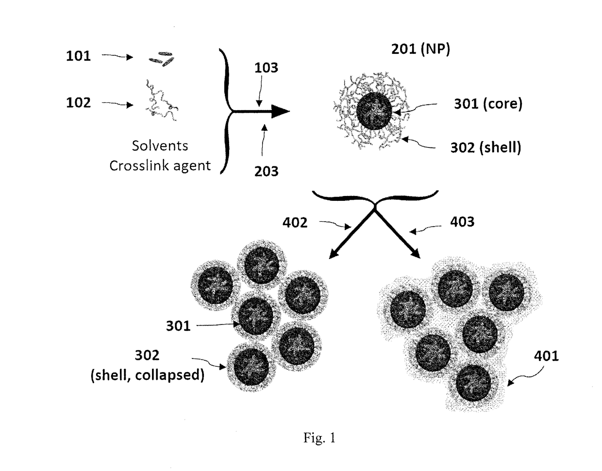
[0114]To produce particles containing hydrophilic compounds, poly(n-butyl acrylate) 7.5 kDa-b-poly(acrylic acid) 5.5 kDa (PBA-b-PAA) and the biologic were first dissolved in a polar organic solvent such as DMSO or methanol. In an FNP process, this stream was rapidly mixed with a less polar nonprocess solvent such as chloroform (CHCl3) or acetone in a CIJ mixer. The non-solvent caused the biologic to precipitate. This precipitation was halted by the self-assembly of the hydrophilic PAA block of the PAA-b-PBA on the growing particle surface. The final particles were sterically stabilized in the non-solvent by the hydrophobic PBA block. The resultant nanoparticle had a core-shell structure.

[0115]This process has been applied to an assortment of model hydrophilic agents with varying molecular weights, including lysozyme as a model protein (14.3 kDa), the cyclic peptide antibiotic vancomycin (1.45 kDa), a model 7-amino acid long peptide (glycine-arginine-leucine-gl...

example 2

cle Loading and Size Control

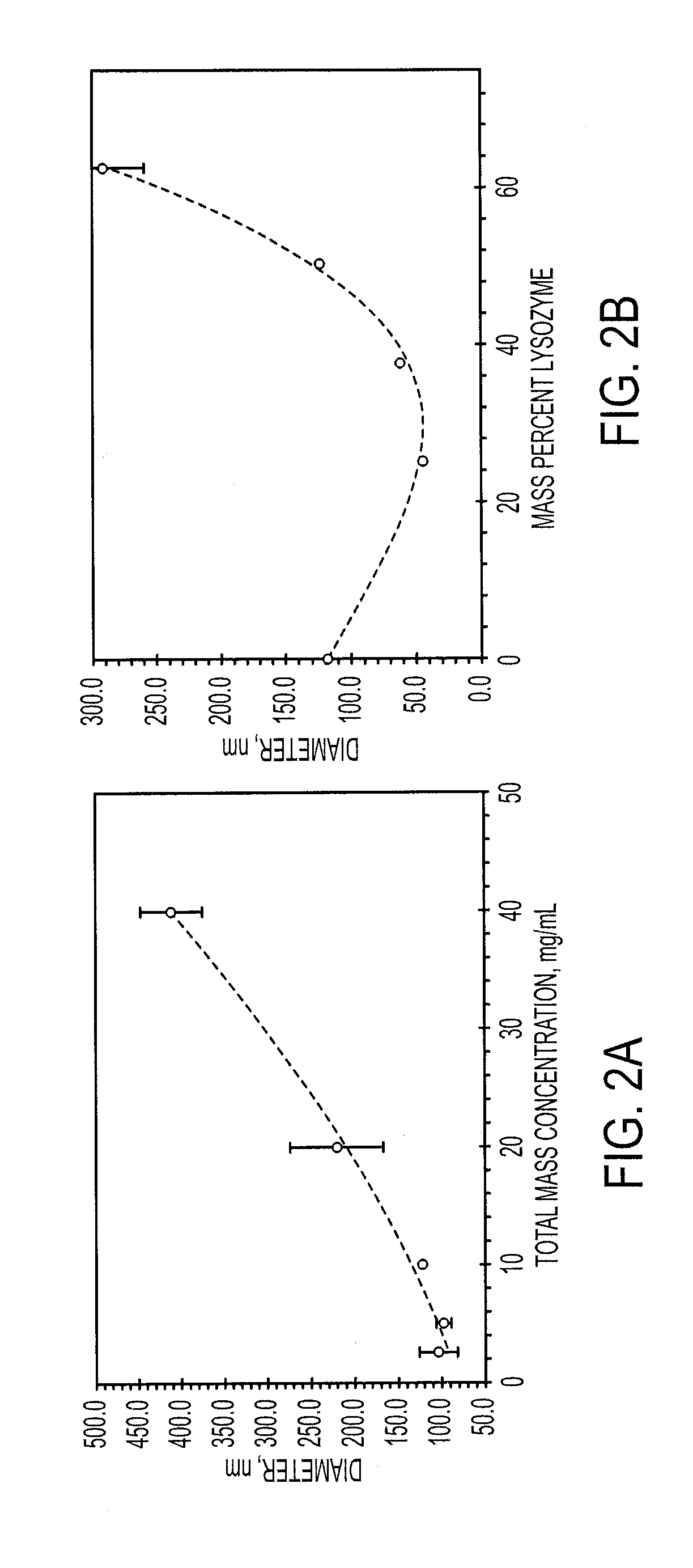
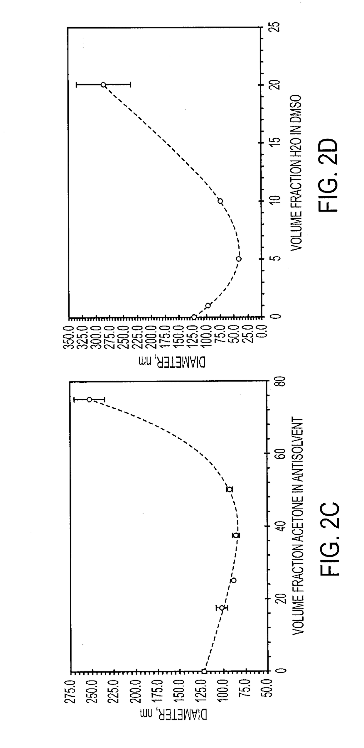
[0116]The sizes of particles produced with FNP may be controlled through the time scales for precipitation of the core material, as well as through the time scale for polymer self-assembly. These time scales are modulated through material concentrations as well as through the choice of nonprocess solvent.

[0117]Increasing the percentage of core material necessitated the formation of larger particles. For both lysozyme and vancomycin, the particle size initially decreased as biologic was added compared to the micelle size of the block copolymer. This may be because the addition of core material allows the PAA to more tightly pack due to charge shielding effects. Very high loadings of both lysozyme and vancomycin were obtained. Loading of lysozyme as high as 75 wt % was obtained without the formation of large precipitates, however, the particles were too large to analyze using dynamic light scattering (DLS). Vancomycin loadings up to 90 wt % resulted in stab...

example 3

tion of Nanoparticles for Further Processing

[0119]In order to stabilize the nanoparticles in aqueous environments and reduce the loss of encapsulated material during processing steps, methods of crosslinking the PAA shell in order to form a gel were investigated. Ionic crosslinking was focused on because it reduces the risk of covalently modifying the encapsulated agent. The anionic PAA side groups may be crosslinked either with multivalent metal cations or polyamines (S. Bontha, A. V. Kabanov, T. K. Bronich, Polymer micelles with cross-linked ionic cores for delivery of anticancer drugs, J. Controlled Release. 114 (2006) 163-174; T. K. Bronich, A. V. Kabanov, V. A. Kabanov, K. Yu, A. Eisenberg, Soluble Complexes from Poly(ethylene oxide)-block-polymethacrylate Anions and N-Alkylpyridinium Cations, Macromolecules. 30 (1997) 3519-3525; T. K. Bronich, P. A. Keifer, L. S. Shlyakhtenko, A. V. Kabanov, Polymer Micelle with Cross-Linked Ionic Core, J. Am. Chem. Soc. 127 (2005) 8236-8237; ...


PUM

PropertyMeasurementUnit
Massaaaaaaaaaa
Massaaaaaaaaaa
Massaaaaaaaaaa

Abstract

An “inverse” precipitation route to precipitate aqueous soluble species with copolymers as nanoparticles having a hydrophilic, polar core and a less polar shell is described. The aggregation of these nanoparticles to form larger microparticles and monoliths provides a highly loaded construct (e.g., a depot) for the sustained and controlled release of actives.

Description

[0001]This application claims the benefit of U.S. Provisional Application No. 62 / 387,075, filed Dec. 22, 2015, the specification of which is hereby incorporated by reference in its entirety.FIELD OF THE INVENTION[0002]The present invention relates to a process of making microparticles comprising aggregated nanoparticles having a hydrophilic core.BACKGROUND OF THE INVENTION[0003]Protein and peptide therapeutics are a growing segment of the pharmaceutical marketplace. In eleven years, from 2001 to 2012, the global sales of pharmaceutical biologic therapeutics (biologics) more than tripled from $36 billion to $163 billion. In that same period, revenue generated by biologics within the top 10 selling pharmaceuticals increased from 7% to 71% (S. Peters, Biotech Products in Big Pharma Clinical Pipelines Have Grown Dramatically, Tufts CSDD Impact Report. 15 (2013) 1). Their specificity makes them ideal therapeutics for the treatment of a variety of diseases including cancer and AIDS. This ...

Claims


Application Information

Patent Timeline
IPC IPC(8): A61K9/50
CPCA61K9/5089A61K9/5031A61K9/5026B01J13/06A61K9/0019A61K9/5138A61K9/5192A61K9/1647A61K9/5146A61K9/5153
Inventor PRUD'HOMME, ROBERT K.PAGELS, ROBERT F.MARKWALTER, CHESTER E.
Owner THE TRUSTEES FOR PRINCETON UNIV
Learn More