Lock pin and bolt construction for securing doors and other closures

a technology of locking pins and bolts, which is applied in the direction of building locks, safes, constructions, etc., can solve the problems of no real changes or improvements to actual lock pins or methods, and achieve the effect of better securing all types of closures

Active Publication Date: 2017-01-10
SHADE RIVER OUTFITTERS
View PDF28 Cites 6 Cited by
  • Summary
  • Abstract
  • Description
  • Claims
  • Application Information

AI Technical Summary

Benefits of technology

[0005]Embodiments of the subject invention are directed towards methods and devices for preventing a door, such as the door of a safe, from being breached by forcibly disengaging one or more lock pins so that they no longer conjoin with the door frame, safe body, or other securing structure around the door. The embodiments of the subject invention successfully address the above described disadvantages associated with the previously known lock pins and provide certain attributes and advantages that have not been realized by other known lock pins utilized in personal, home or commercial safes. The lock pin embodiments disclosed herein provide a novel, inexpensive, and convenient solution for better securing all types of closures against forcible entry.
[0010]Another embodiment provide a curvature of rotation by employing a lock pin having a non-circular circumferential shape, where the lock pin is also twisted between the proximal end and distal ends. This provides a lock pin with a linear curvature between the two ends. When mated with a compatibly shaped key hole and / or pin hole, the lock pin can turn as it advances through a hole. This can cause the same effect as a cam guide and groove described above, where the distal end is turned or rotated from its original position, as the locking mechanism is operated and the lockpins are moved linearly.
[0012]Often, when a home safe is breached, it is because the door was bent or pried sufficiently out of alignment to disengage one or more lock pins from the door frame. An alternative breach strategy is to drill one or more holes into the side of a home safe in a location that allows access to at least one lock pin. Because, in a typical home safe, all of the lock pins on each side of a door are attached to carriages, forcibly pushing just one lock pin back away from the door frame can, with some safes, simultaneously move all of the lock pins on that carriage, thereby simultaneously disengaging all of them from the door frame. Once all of the lock pins on a carriage are pushed back, the door can be easily opened after the locking mechanism is defeated.
[0013]One advantage of the lock pin embodiments of the subject invention is their ability to inhibit disengagement from their abutment against or across the door frame on the safe body by bending the lock pins themselves or bending other components in the safe to which the lock pin is attached. Because they can be secured at both ends to other components of the safe, it is more difficult to move or pry them away from the safe body, door frame, or other structures in the safe. Thus, attempting to bend or move the lock pins of the subject invention away from the door frame can entail also bending other components of the safe as well, such as the door or the carriage.
[0015]The embodiments of the subject invention successfully address the above described disadvantages associated with the previously known lock pin, particularly lock pins in safes, by providing devices and methods with certain attributes and advantages that have not been previously realized with known lock pins. In particular, the subject invention provides novel, inexpensive, and highly effective devices and methods for conveniently and more effectively engaging lock pins with a safe body or other structure. The embodiments disclosed herein can be incorporated with existing devices or mechanism, such as those on a safe, without having to alter, adjust, or otherwise change the locking mechanism of the device or mechanism.

Problems solved by technology

But, it has been shown that persistent effort with simple tools can effectively bend the door, bolt carriage, and / or the locking bolts so they no longer abut or contact the door frame, allowing access to the safe interior.
However, there have been no real changes or improvements to the actual lock pins or methods by which lock pins can engage with the door frame or safe body to secure the door to the housing.

Method used


Image

  • Lock pin and bolt construction for securing doors and other closures
  • Lock pin and bolt construction for securing doors and other closures
  • Lock pin and bolt construction for securing doors and other closures

Examples


Embodiment Construction

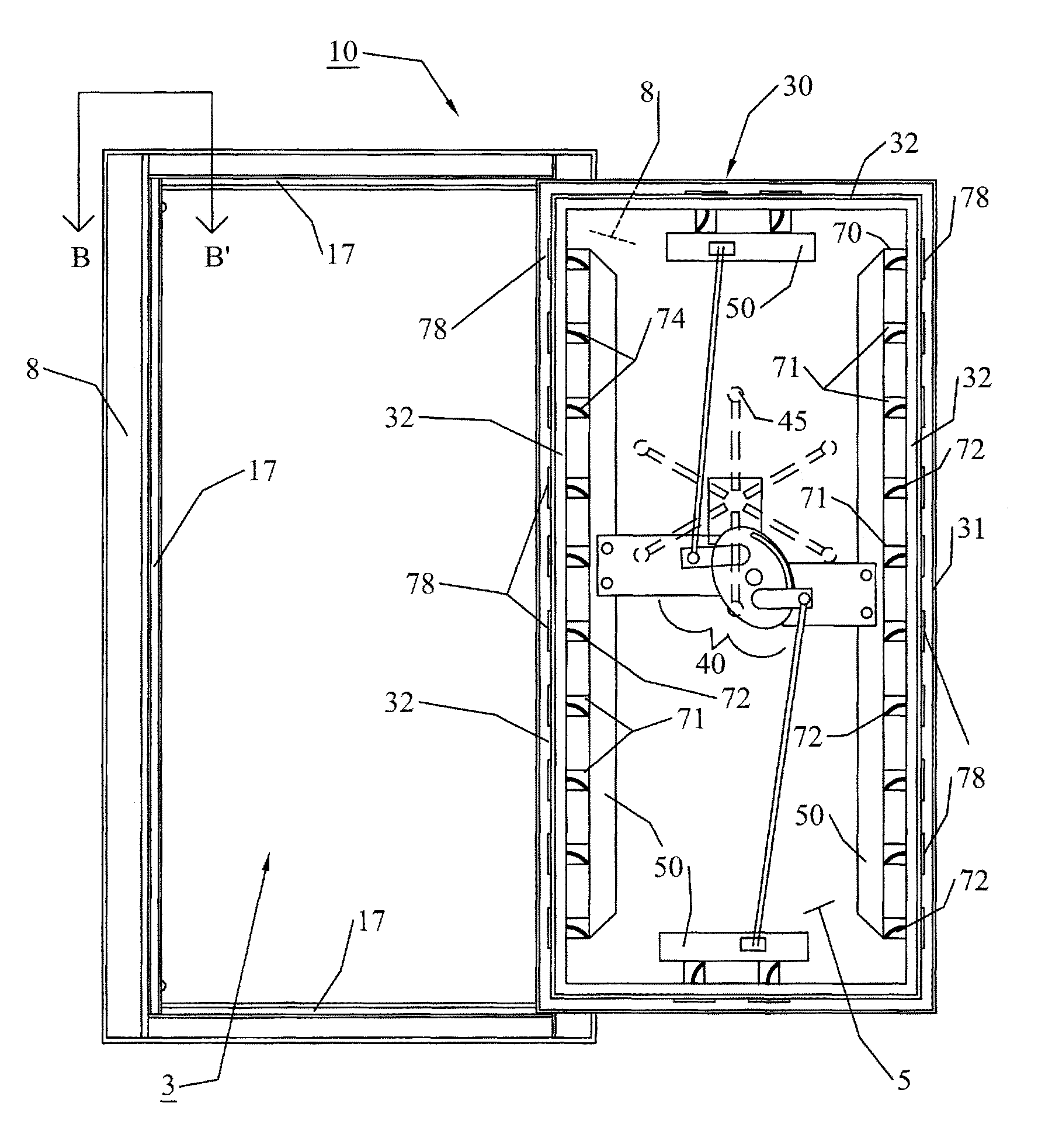
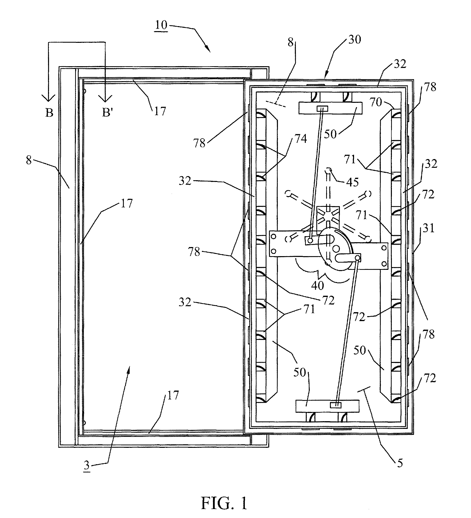
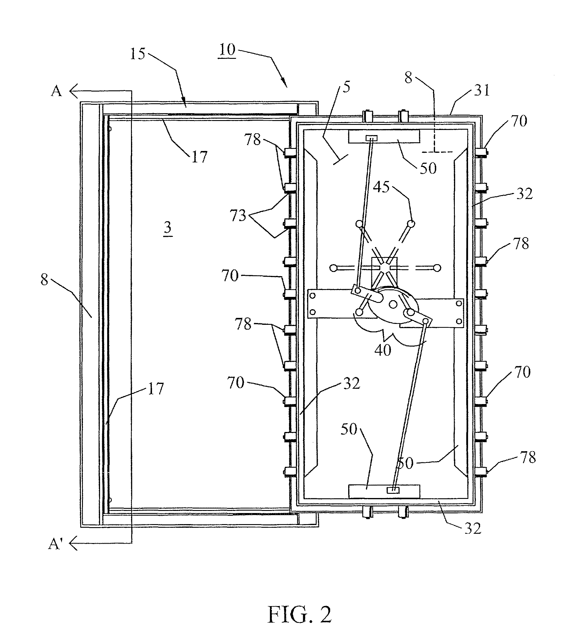
[0037]The subject invention describes embodiments of a unique lock pin system that can be used with doors, lids, and other closures on rooms, containers, safes, or other devices or mechanisms that employ a lock pin or bolt to secure the position of a structure on the device or mechanism, such as, for example, the door on a safe. More specifically, the subject invention provides one or more embodiments of lock pins utilized with safes, such as residential security containers or larger commercial safes, or similar devices, where the lock pins are capable of being more securely attached to the safe body and are inhibited from being moved, damaged, or otherwise altered, so that they no longer operate to secure the door of a safe. More specifically, the embodiments of the subject invention allow at least two ends of a lock pin to be secured to inhibit bending of the lock pin or prying of the lock pin out of a position that allows it to secure the container.

[0038]The following description...


PUM


Abstract

A rotatable lock pin that inhibits forced entry into a container through a closure by securing the lock pin to the container. A lock pin has a pin cylinder with a curvature of rotation that engages with a rotation facilitator. The path of the curvature of rotation and the engagement of the rotation facilitator therewith causes the lock pin to rotate in a pre-determined fashion, so that structures on the lock pin can engage or attach to some part of the container to secure the position of the lock pin and hold the closure door in place. Lock pins of the subject invention utilized with safes can inhibit forced entry through the door by side punching or prying of the door.

Description

CROSS-REFERENCE TO A RELATED APPLICATION[0001]This application claims the benefit of U.S. Provisional Application Ser. No. 62 / 128,660, filed Mar. 5, 2015, and U.S. Provisional Application Ser. No. 62 / 042,449, filed Aug. 27, 2014, the disclosures of which are hereby incorporated by reference in their entireties, including all figures, tables, and drawings.BACKGROUND OF INVENTION[0002]Residential security containers are increasingly popular in use, particularly the larger styles often referred to as “gun safes” or “home safes.” One of the most common styles of home safe is an upright, rectangular, free-standing structure, with a front opening door. These home safes usually have a safe body with a door frame defining an opening that leads to an interior space and a door attached to the safe body by hinges that swings into the opening in the door frame.[0003]Most types of safes, including commercial safes and larger home safes, have a hand wheel or lever on the exterior side of the door...

Claims


Application Information

Patent Timeline
Patent Type & Authority Patents(United States)
IPC IPC(8): E05G1/04E05C5/04E05B15/10E05B63/12E05C5/02E05B65/00
CPCE05B15/102E05B63/125E05B65/0075E05C5/02E05C5/04E05G1/04E05B2015/107E05C9/16E05C9/06
Inventor GARRETT, NICHOLAS JOHN
Owner SHADE RIVER OUTFITTERS
Why Eureka
Try Eureka