Controlled decoration of carbon nanotubes with aerosol nanoparticles

Inactive Publication Date: 2012-08-16
UMW RES FOUND INC
View PDF0 Cites 4 Cited by
  • Summary
  • Abstract
  • Description
  • Claims
  • Application Information

AI Technical Summary

Benefits of technology

[0017]It is thus another object of the invention to provide an assembly technique that by allowing great flexibility in the types and composition of nanoparticles being used is widely applicable to applications such as: filtration, sensing, purif

Problems solved by technology

These methods, however, are generally very slow and the associated interfacial chemistry is material dependent, limiting their ability to create nanostructures of arbitrary

Method used


Image

  • Controlled decoration of carbon nanotubes with aerosol nanoparticles
  • Controlled decoration of carbon nanotubes with aerosol nanoparticles
  • Controlled decoration of carbon nanotubes with aerosol nanoparticles

Examples


Example

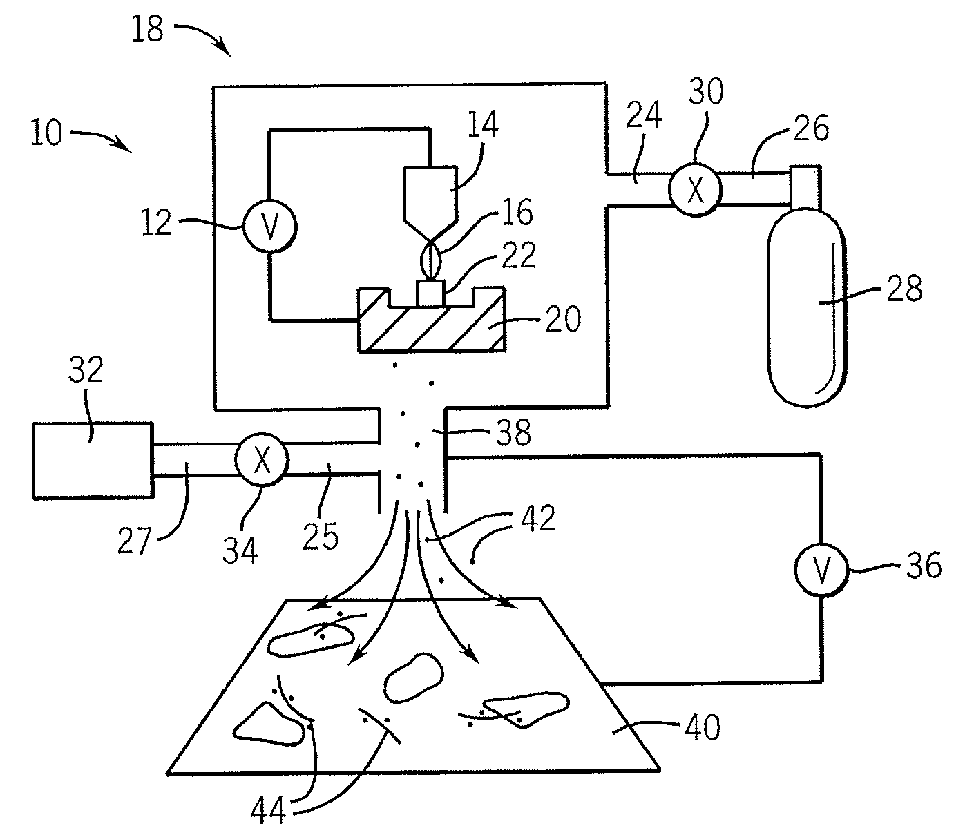
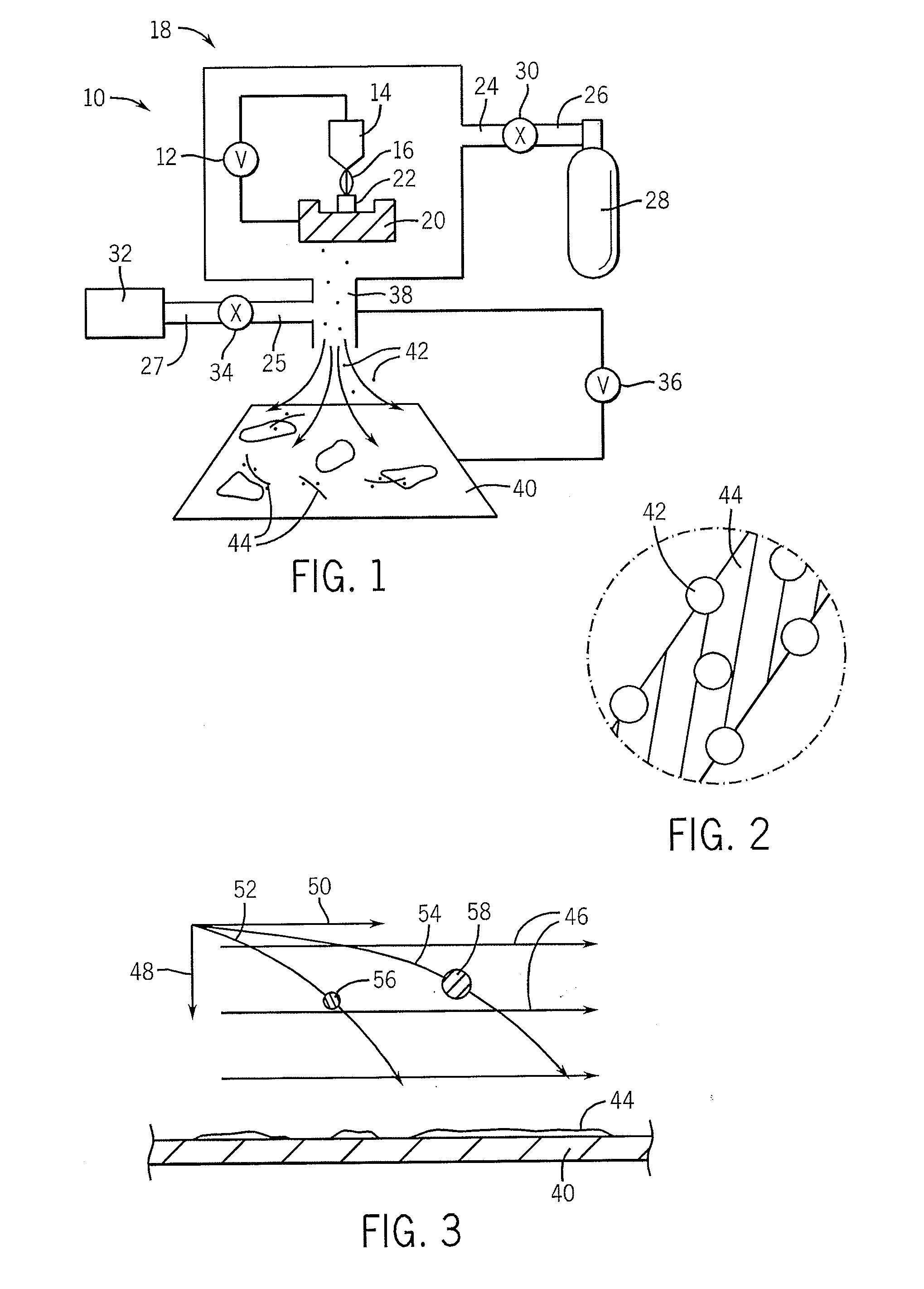
[0032]Referring to FIG. 1, an electrostatic force directed assembly (ESFDA) device 10 provides an arc plasma source chamber 18 enclosing an arc cathode 14 opposed to an arc anode 20, the later holding a precursor material 22 from which nanoparticles will be created. A plasma arc voltage source 12 couples the arc anode 20 to the arc cathode 14 to create the arc 16 which strikes the precursor material 22 for the production of the nanoparticles 42. The arc cathode 14 and arc anode 20 may be, for example, tungsten and graphite respectively.

[0033]The application of the arc 16 to the precursor material 22 creates an aerosol of nanoparticles 42 through physical vaporization of the solid precursor material 22. This generation of nanoparticles creates a relatively broad size distribution of nanoparticles 42. A significant fraction of the nanoparticles 42 are charged by the arc 16 or through plasma or thermionic emission, which makes ESFDA feasible without the use of further nanoparticle 42 c...


PUM


Abstract

The present invention addresses the problem of conveniently and efficiently decorating nanostructures such as carbon nanotubes with aerosol nanoparticles using electrostatic force directed assembly (“ESFDA”). ESFDA permits size selection as well as control of packing density spacing of nanoparticles. ESFDA is largely material independent allowing different compositions of such nanoparticle-nanotube structures to be produced.

Description

CROSS REFERENCE TO RELATED APPLICATIONS[0001]This application claims the benefit of U.S. provisional application 60 / 710,642 filed on Aug. 23, 2005, hereby incorporated by reference.STATEMENT REGARDING FEDERALLY SPONSORED RESEARCHBACKGROUND OF THE INVENTION[0002]The present invention relates to the assembly of nanoparticles, and, in particular, to a method of using electrostatic force to assemble nanoparticles onto nanostructures.[0003]The manufacture of nanostructures from carbon nanotubes and nanoparticles may be useful in a broad range of applications including: nanoelectronics, chemical sensors, biosensors, catalysis, fuel cells, and hydrogen storage. Current methods for assembling these components are primarily based on “wet-chemical” techniques in which the components are created or manipulated with chemical reactions taking place in solution. These methods, however, are generally very slow and the associated interfacial chemistry is material dependent, limiting their ability t...

Claims


Application Information

Patent Timeline
IPC IPC(8): B05D5/12B82Y99/00
CPCB82Y40/00
Inventor CHEN, JUNHONGLU, GANHUA
Owner UMW RES FOUND INC
Why Eureka
Try Eureka