
Multi-port measurement technique

a multi-port, measurement technology, applied in the direction of resistance/reactance/impedence, instruments, measurement devices, etc., can solve the problems of many connections and disconnections, difficult or simply not possible to access all of them simultaneously, and almost impossible to realize at rf frequencies

Active Publication Date: 2016-10-06
ADVANTEST CORP
View PDF1 Cites 4 Cited by
  • Summary
  • Abstract
  • Description
  • Claims
  • Application Information

AI Technical Summary

Benefits of technology

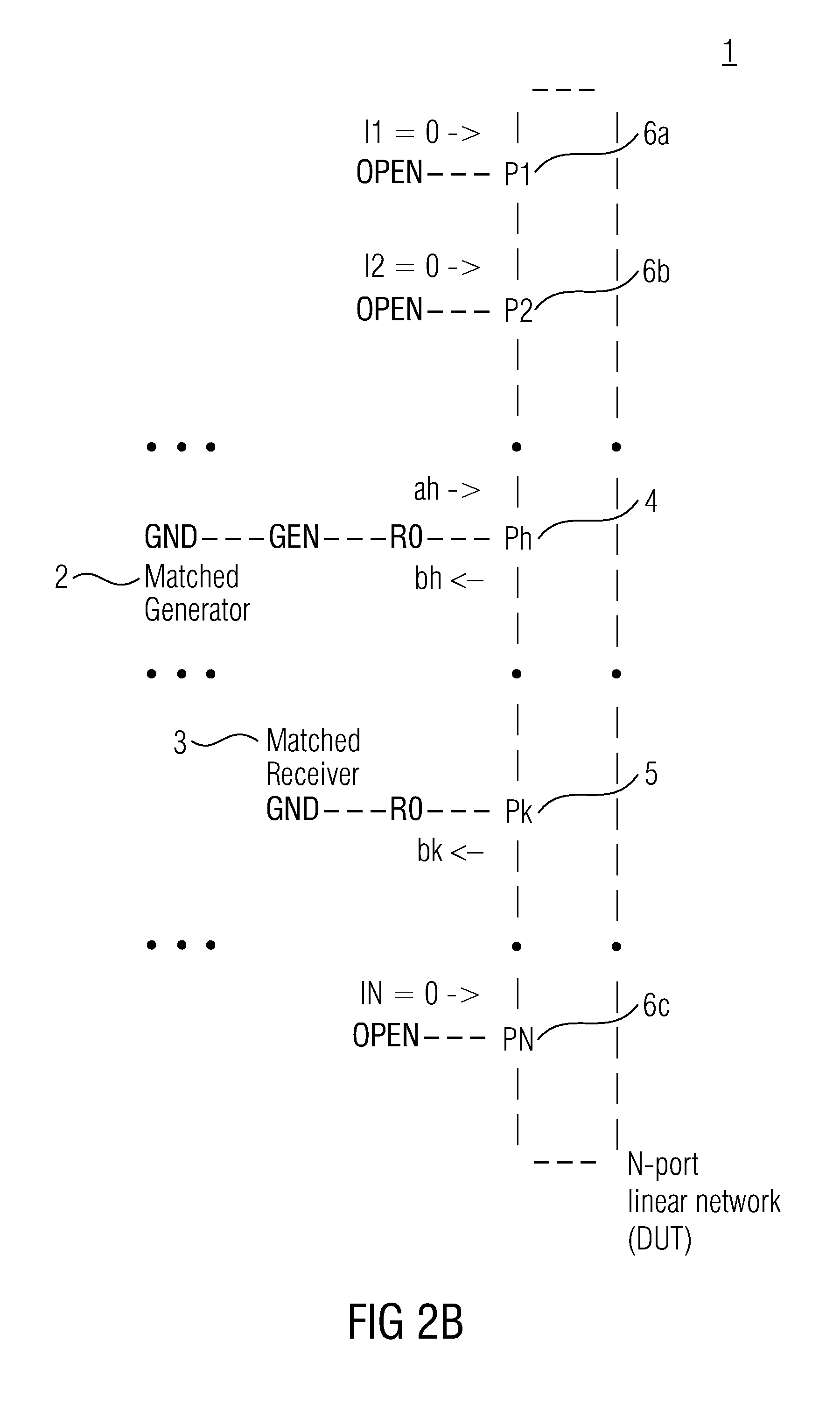
The invention provides an improved solution for calculating the S-parameters of a linear network by using only two ports for measurements, even if the actual impedance at one or more of the other ports may have a relatively large deviation from R0. This advancement makes it possible to analyze the performance of electronic chips that have a large number of ports and a small distance between them. The invention also provides a chip tester that can calculate one or more S-parameters of a semiconductor microchip, representing a linear network, even if during the measurement of an electrical response one or more of the other ports of the semiconductor microchip face a reflection coefficient with an amplitude ρ of 0.5 or larger.

Problems solved by technology

A current generator is needed, which is almost impossible to realize at RF frequencies.
This brings the problem that many connections and disconnections may be used, although they can be automated by means of switching circuitry as known from multi-port network analyzers.
Sometimes the DUT is so small and the ports are so many and so close, that it is very difficult or simply not possible to access all of them simultaneously.
Calculating the S-parameters of a linear network having three or more ports can be very time-consuming and difficult.
Especially if the DUT has a linear network with ports very close to each other and a high number of ports measuring the electric response at each port can be a difficult task.
Such apparatuses are known for example from the chip industry and there is a large demand for improving time-consuming and difficult determinations of S-parameters.
In addition the number of ports on a given surface of the chip is often very large.
Thus, there may be only a small distance between two ports so that it can become extremely difficult to terminate all other ports with a resistance corresponding to R0 with a ρ equal to or smaller than 0.3, the other ports not being used for generating an incident wave or measuring an electrical response during a measurement.

Method used


Image

  • Multi-port measurement technique
  • Multi-port measurement technique
  • Multi-port measurement technique

Examples


Embodiment Construction

[0056]The invention is described in detail with regards to FIG. 1 to FIG. 8. The invention is in no way meant to be limited to the shown and described embodiment.

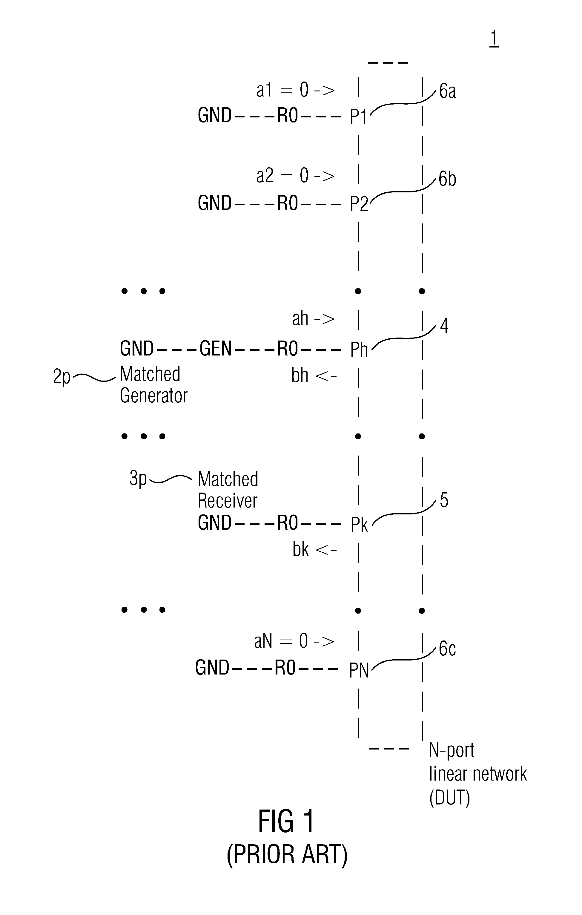
[0057]FIG. 1 shows a first N-port linear network 1 connected to a conventional setup in order to perform a conventional calculation of S-parameters. An apparatus (not shown) is configured to calculate one or more scattering parameters of the N-port linear network 1, the N-port linear network 1 comprising a number of N ports adapted to provide electric connections. The conventional setup comprises a matched generator 2p for generating an incident wave, the matched generator 2p comprising a first matched receiver (not shown) for measuring an electrical response and a bridge. In other embodiments, the bridge may be replaced by a directional coupler. The conventional setup furthermore comprises a second matched receiver 3p being separate from the matched generator 2p that comprises the first matched receiver. The matched genera...


PUM


Abstract

This invention relates to an apparatus, a method and a computer program for calculating one or more scattering parameters of a linear network, the network including a number of N ports adapted to provide electric connections. The apparatus is configured to calculate, and the method includes calculating, one or more scattering parameters of the linear network, which are related to a reference impedance, on the basis of a measured electrical response at one or more ports of the linear network to an incident wave applied at a port of the linear network, measured under the condition that one or more of other ports of the linear network face a reflection coefficient Γ with an amplitude ρ of 0.5 or larger. The computer program is adapted to perform such a method and runs on a computer.

Description

CROSS-REFERENCE TO RELATED APPLICATIONS[0001]This application is a continuation of copending International Application No. PCT / EP2013 / 077839, filed Dec. 20, 2013, which is incorporated herein by reference in its entirety.[0002]Embodiments of the invention refer to an apparatus for calculating one or more scattering parameters of a linear network, to a method for calculating one or more scattering parameters of a linear network, and to a computer program for performing such a method, when the computer program runs on a computer.BACKGROUND OF THE INVENTION[0003]In general, apparatuses, computer programs, and methods for calculating one or more scattering parameters of a linear network are known. A N-port linear network has many equivalent representations. Two of them are the impedance matrix and the scattering matrix. The first one uses voltage and currents, as illustrated at the linear network in FIG. 8a, and can be more useful for calculations, the latter uses linear combinations of...

Claims


Application Information

Patent Timeline
IPC IPC(8): G01R27/28
CPCG01R27/28G01R27/32
Inventor BIANCHI, GIOVANNI
Owner ADVANTEST CORP
Learn More