Eureka AIR delivers breakthrough ideas for toughest innovation challenges, trusted by R&D personnel around the world.

Semiconductor structure with oval shaped conductor

Active Publication Date: 2017-01-10
TAIWAN SEMICON MFG CO LTD
View PDF15 Cites 2 Cited by
  • Summary
  • Abstract
  • Description
  • Claims
  • Application Information

AI Technical Summary

Benefits of technology

The present patent text discusses the challenges of improving bump connections in semiconductor structures, especially in the case of warped substrates. The text describes a method for improving bump connections by extending the landing area for receiving conductive bumps. This method uses oval-shaped bumps that are difficult to crack, even if the substrate is warped. The technical effect of this method is to improve the reliability and performance of semiconductor structures by improving bump connections.

Problems solved by technology

A large substrate in WLP technology raises concerns about bump connections, especially at the peripheral region of such substrate.
Some factors may lead to warpage of the substrate, thereby failing to achieve bump connections between the substrate and a board connected therewith.
Since the bump connections in the WLP technology is poorly controlled, improvements in the method for a WLP continue to be sought.

Method used


Image

  • Semiconductor structure with oval shaped conductor
  • Semiconductor structure with oval shaped conductor
  • Semiconductor structure with oval shaped conductor

Examples


Embodiment Construction

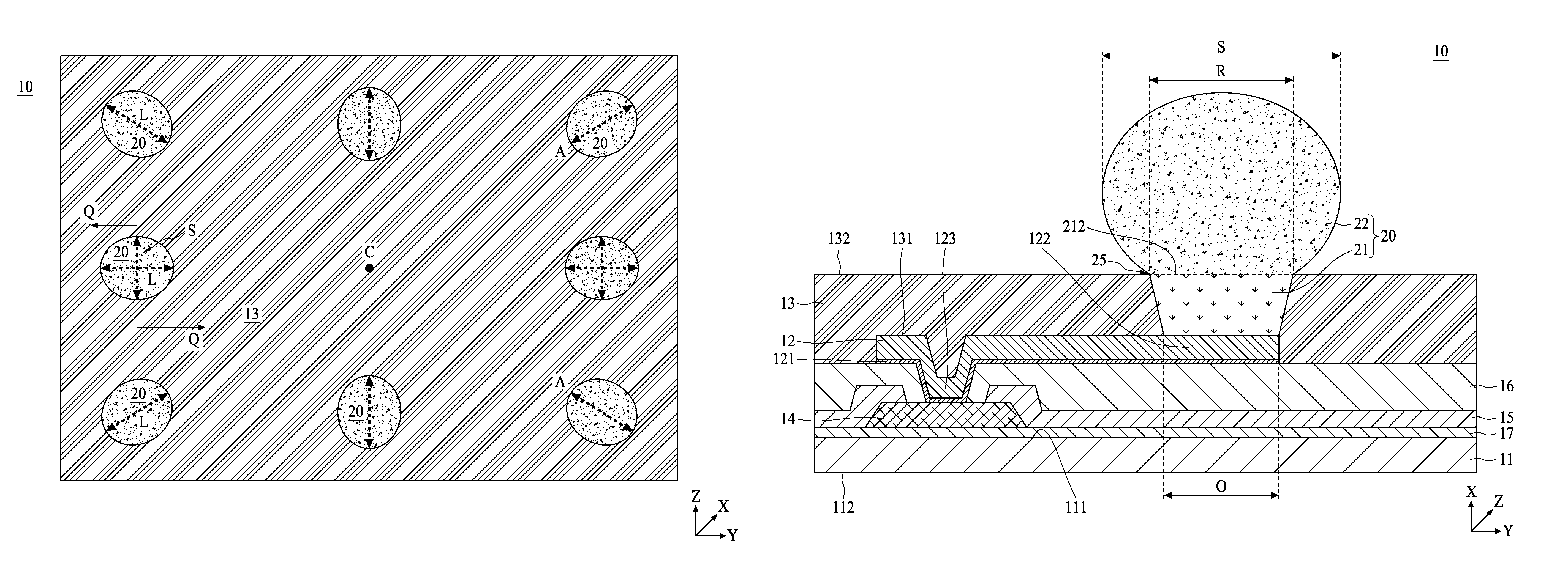
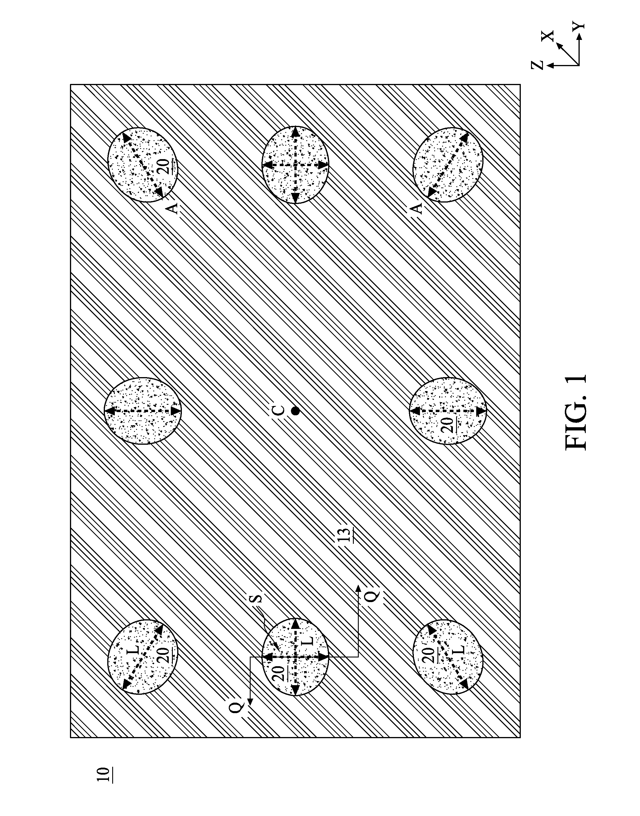
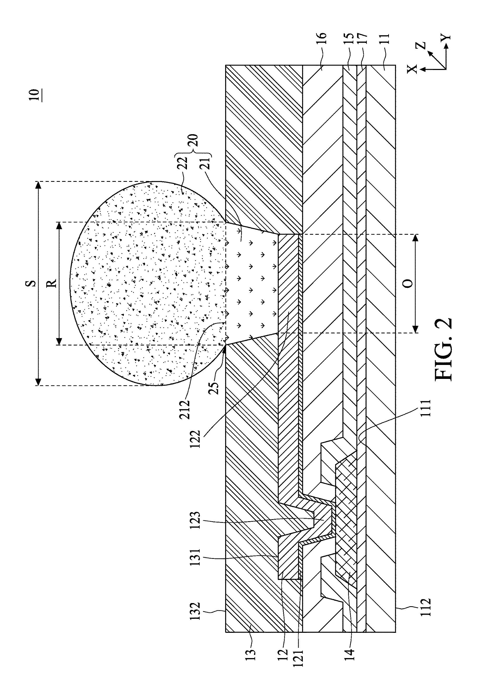
[0011]The following disclosure provides many different embodiments, or examples, for implementing different features of the provided subject matter. Specific examples of components and arrangements are described below to simplify the present disclosure. These are, of course, merely examples and are not intended to be limiting. For example, the formation of a first feature over or on a second feature in the description that follows may include embodiments in which the first and second features are formed in direct contact, and may also include embodiments in which additional features may be formed between the first and second features, such that the first and second features may not be in direct contact. In addition, the present disclosure may repeat reference numerals and / or letters in the various examples. This repetition is for the purpose of simplicity and clarity and does not in itself dictate a relationship between the various embodiments and / or configurations discussed.

[0012]I...


PUM


Abstract

A semiconductor structure includes a semiconductive substrate, a post passivation interconnect (PPI) and a polymer layer. The PPI is disposed above the semiconductive substrate and includes a landing area for receiving a conductor. The polymer layer is on the PPI, wherein the conductor is necking a turning point so as to include an oval portion being substantially surrounded by the polymer layer, and the oval portion of the conductor is disposed on the landing area of the PPI.

Description

BACKGROUND[0001]Presently, electronic equipment is essential for many modern applications. Therefore, consumers are increasingly demanding more processing power, lower electrical power usage and cheaper devices. As the electronic industry strives to meet these demands and more complicated and denser configurations, miniaturization will result in an extension of the number of chips per wafer and the number of transistors per chip, as well as a reduction in power usage. Wafer level packaging (WLP) technology has been gaining popularity since the electronic components are being designed to be lighter, smaller, more multifunctional, more powerful, more reliable and less expensive. The WLP technology combines dies having different functionalities at a wafer level, and is widely applied in order to meet continuous demands toward the miniaturization and higher functions of the electronic components.[0002]A large substrate in WLP technology raises concerns about bump connections, especially...

Claims


Application Information

Patent Timeline
IPC IPC(8): H01L23/00H01L21/3105H01L21/56H01L23/31H01L21/66
CPCH01L24/03H01L21/31053H01L21/56H01L22/12H01L23/3157H01L23/3171H01L23/3192H01L24/02H01L24/05H01L24/13H01L24/14H01L24/11H01L24/16H01L2224/0235H01L2224/0239H01L2224/02311H01L2224/02313H01L2224/02331H01L2224/039H01L2224/0332H01L2224/0384H01L2224/0391H01L2224/03334H01L2224/03462H01L2224/0401H01L2224/056H01L2224/05008H01L2224/05569H01L2224/119H01L2224/11849H01L2224/131H01L2224/13014H01L2224/13022H01L2224/13024H01L2224/13116H01L2224/13118H01L2224/13124H01L2224/13144H01L2224/13147H01L2224/1412H01L2224/16227H01L2224/16238H01L2224/92H01L2924/00012H01L2924/01079H01L2924/01047H01L2924/01029H01L2924/01028H01L2924/01074H01L2924/01013H01L2924/01022H01L2924/04941H01L2924/01073H01L2924/04953H01L2924/0496H01L2924/014H01L2924/00014H01L2224/0231H01L2224/03H01L2224/11H01L23/562H01L2224/14145H01L2924/3511H01L2924/3512H01L2224/02181H01L2224/0219H01L2224/02375H01L2224/05025H01L2224/05124H01L2224/05139H01L2224/05144H01L2224/05147H01L2224/05155H01L2224/05184H01L2224/10126H01L2224/11462H01L2224/11602H01L2224/13082
Inventor CHIANG, YUNG-PINGSHIH, CHAO-WENTSAI, HAO-YILII, MIRNG-JI
Owner TAIWAN SEMICON MFG CO LTD
Why Eureka
Eureka Blog
Learn More