Medical device locking mechanisms and related methods and systems

a technology for locking mechanisms and medical devices, applied in the direction of osteosynthesis devices, fasteners, bone plates, etc., can solve the problems of ineffectiveness of many of these locking mechanisms, reverse threading or backing out is obviously problematic, screw reversing tends to reverse, etc., to achieve robust, simple and inexpensive locking and/or anti-backout, and effective performance

Active Publication Date: 2017-01-17
CTL MEDICAL CORP
View PDF69 Cites 3 Cited by
  • Summary
  • Abstract
  • Description
  • Claims
  • Application Information

AI Technical Summary

Benefits of technology

[0006]In various exemplary embodiments, the present invention provides such a robust, simple, and inexpensive locking and / or anti-backout mechanism for a screw and / or other fastener of a plate or other medical implant or device. Various embodiments may be elegant in design and effective in performance. Some embodiments may utilize a plate with holes one or more of which may comprise a locking lip structure and / or receiving well, and locking screws that may incorporate a head portion having petal structures that are outwardly biased prior to insertion via an internally-disposed c-ring or another similar biasing member. Advantageously, in some embodiments, the lead-in torque of each of the locking screws is less than the lead-out torque of each of the locking screws. Thus, reverse threading or backing out is prevented.

Problems solved by technology

Absent some sort of locking mechanism, these bone screws tend to reverse thread, or back out, over time.
This reverse threading or backing out is obviously problematic.
Many of these locking mechanisms are ineffective, overly complicated, cumbersome to implement, and / or unnecessarily expensive.

Method used


Image

  • Medical device locking mechanisms and related methods and systems
  • Medical device locking mechanisms and related methods and systems
  • Medical device locking mechanisms and related methods and systems

Examples


Embodiment Construction

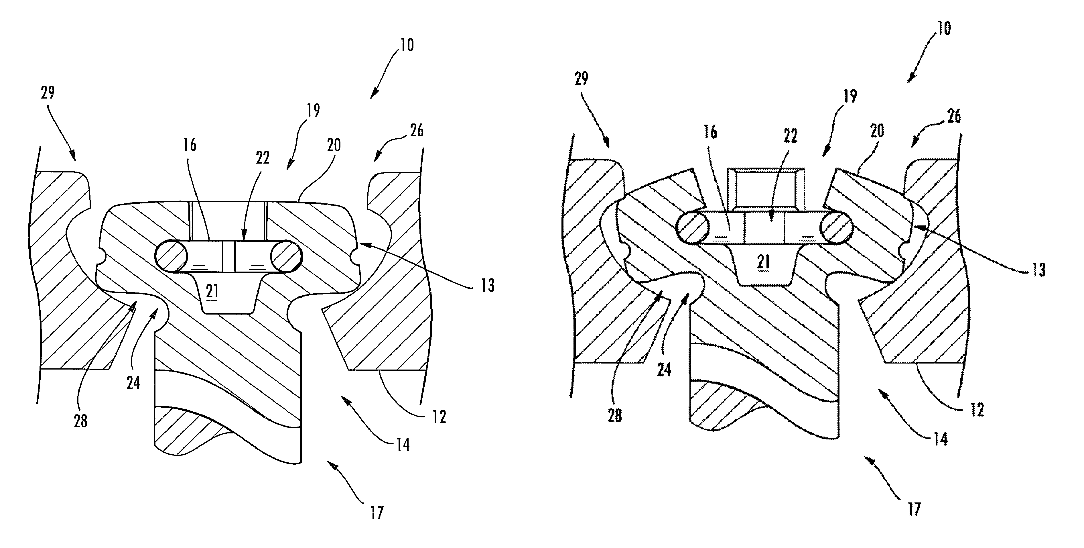
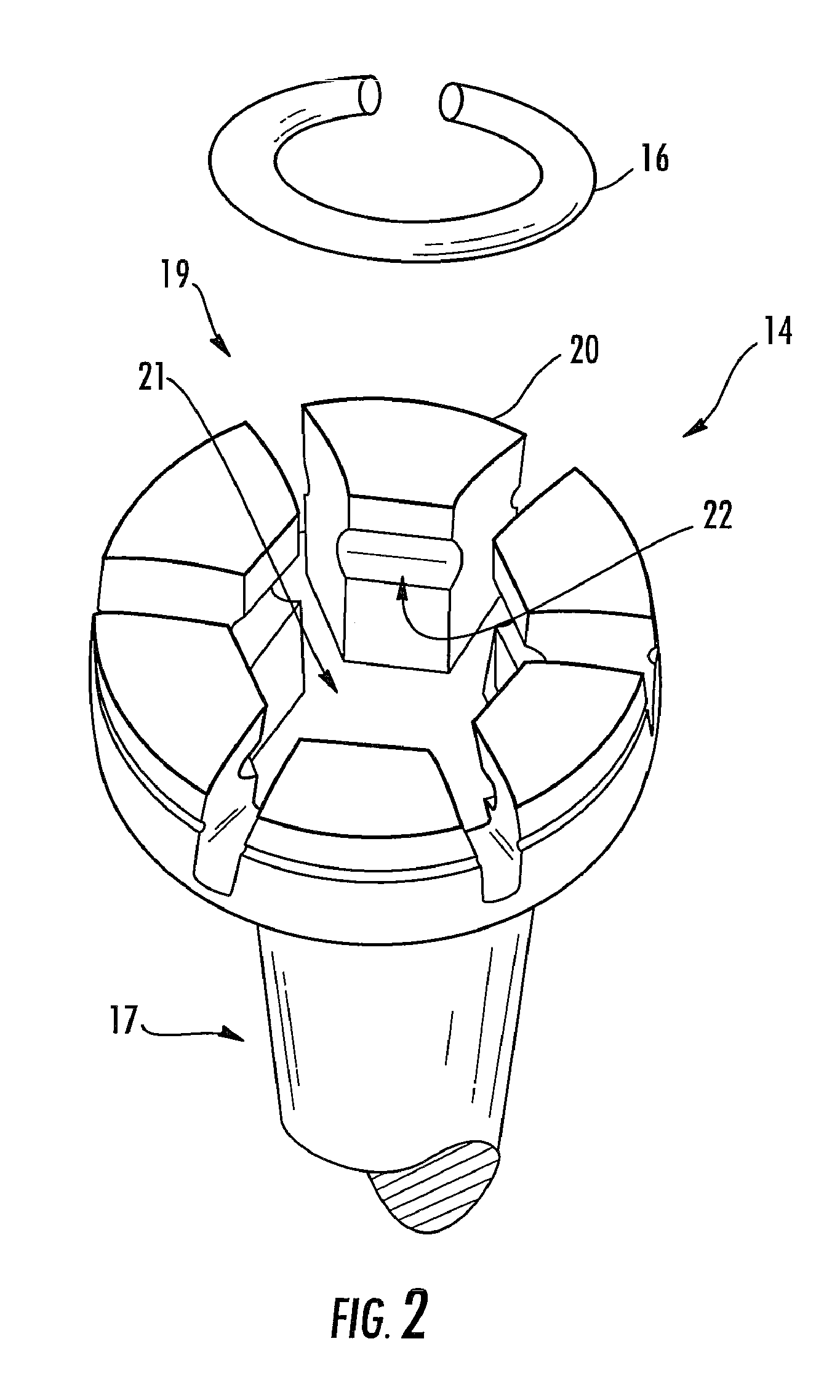
[0038]As described above, in various exemplary embodiments, the present invention provides a robust, simple, and inexpensive locking and / or anti-backout mechanism. Some embodiments may be elegant in design and effective in performance, and may utilize a plate with holes that each incorporate a locking lip structure and / or receiving well. Associated locking screws may each incorporate a head portion having petal structures that are outwardly biased prior to insertion via an internally-disposed c-ring or the like. Advantageously, in some embodiments, the lead-in torque of each of the locking screws is less than the lead-out torque of each of the locking screws. Thus, reverse threading or backing out may be prevented.

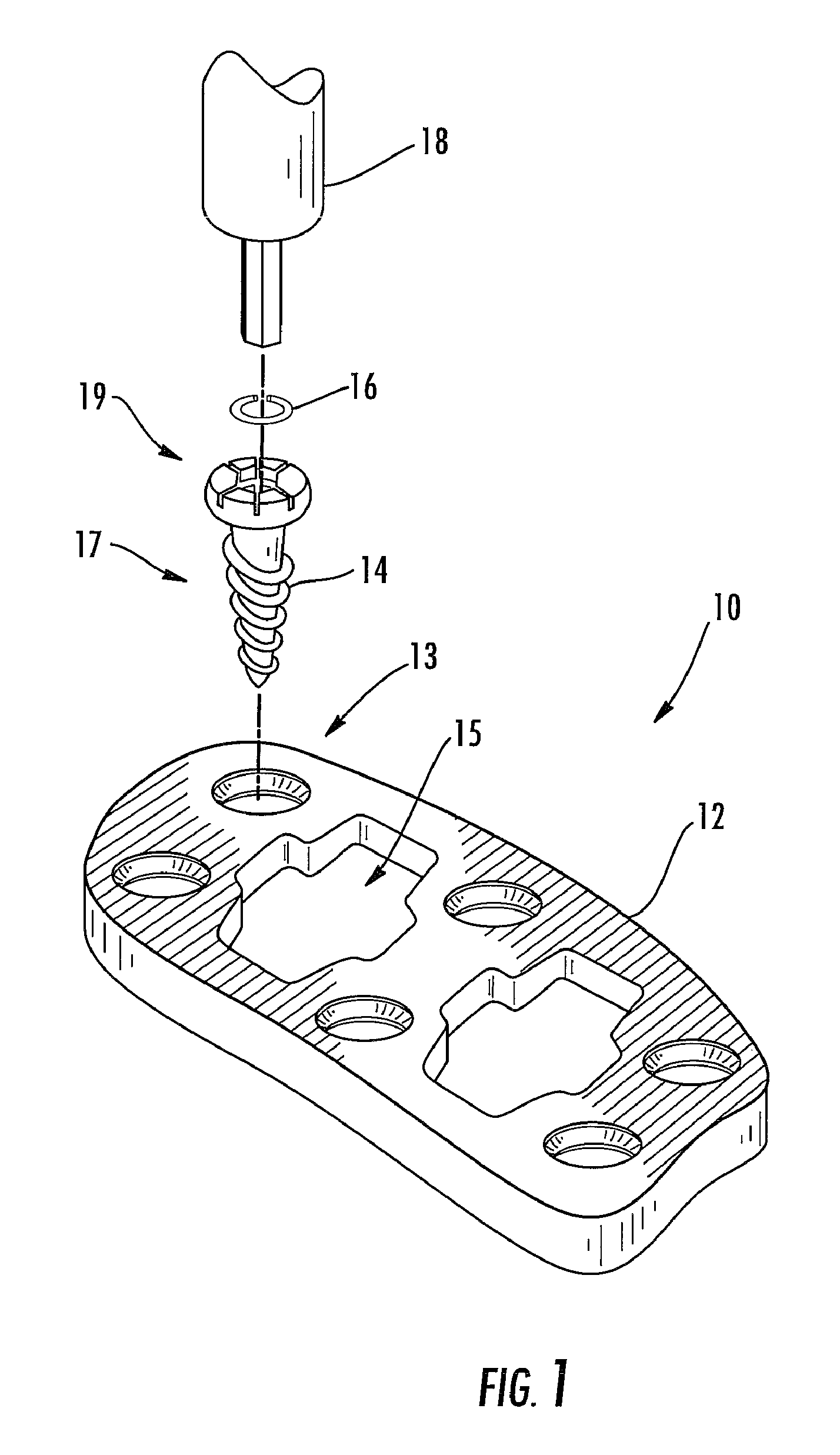
[0039]FIG. 1 is an exploded perspective view of one exemplary embodiment of a cervical plate locking mechanism 10 of the present invention (being installed using a keyed tool, such as a keyed screwdriver 18 or the like), the cervical plate locking mechanism 10 including bo...


PUM


Abstract

Medical device locking mechanisms and related methods and systems. In some embodiments, the medical device may comprise an outer surface defining one or more fastener openings configured for receiving one or more fasteners. The one or more fasteners may comprise an upper surface configured to be engaged by a component of the locking system to prevent fastener backout. A plurality of petal structures may be configured to be selectively expanded or contracted to engage the head portion and retain the at least one fastener within the fastener opening to prevent the fastener from backing out of the fastener opening. A biasing member may selectively engage the plurality of petal structures to either expand or contract the plurality of petal structures to facilitate locking the fastener(s) in place within the device.

Description

RELATED APPLICATIONS[0001]This application is a continuation-in-part of co-pending U.S. patent application Ser. No. 11 / 875,072, filed on Oct. 19, 2007, and titled “CERVICAL PLATE LOCKING MECHANISM AND ASSOCIATED SURGICAL METHOD”, which is a continuation-in-part of U.S. patent application Ser. No. 11 / 804,545, filed on May 18, 2007, and titled “CERVICAL PLATE LOCKING MECHANISM AND ASSOCIATED SURGICAL METHOD.” Both of the foregoing applications are hereby incorporated by reference herein in their entireties.FIELD OF THE INVENTION[0002]Some embodiments disclosed herein relate generally to locking and / or anti-backout mechanisms for various medical devices and / or implants, and related methods. For example, various features and / or components of embodiments disclosed herein may be incorporated into and / or used in conjunction with various implants, including cervical plates, thoracolumbar fixation plates, anterior lumbar fixation plates, standalone interbody devices, bone fracture fixation p...

Claims


Application Information

Patent Timeline
Patent Type & Authority Patents(United States)
IPC IPC(8): A61B17/84A61B17/86A61B17/70A61B17/80
CPCA61B17/8038A61B17/7059A61B17/8033A61B17/8047A61B17/8052A61B17/8605A61B17/7055
Inventor CAWLEY, TRACE R.CROOK, DAVID
Owner CTL MEDICAL CORP
Why Eureka
Try Eureka