
Light distribution control method and light distribution control device for a vehicular headlamp

a technology for controlling the light distribution of a vehicular headlamp and the control method, which is applied in the direction of fixed installation, lighting and heating equipment, transportation and packaging, etc., can solve the problems of difficult to completely eliminate the deviation between the detected position of a vehicle ahead, the dazzling of the driver etc. of the vehicle ahead, and the processing of reducing the light quantity in the illumination region can be simplified, and the response speed is high. , the effect of reducing the light quantity of the determined

Active Publication Date: 2017-01-24
KOITO MFG CO LTD
View PDF40 Cites 8 Cited by
  • Summary
  • Abstract
  • Description
  • Claims
  • Application Information

AI Technical Summary

Benefits of technology

The invention relates to a method for controlling the distribution of light from headlamps in a vehicle. The technical effects of the invention include absorbing errors in the position detection of the vehicle, simplifying processing for reducing light quantity in illumination regions where a vehicle ahead exists, and preventing dazzling of the driver etc. of the vehicle ahead. Additionally, the invention can prevent dazzling of the driver etc. due to light emitted from the right headlamp and from a distant vehicle.

Problems solved by technology

In particular, systems that perform an ADB light distribution control are associated with various kinds of errors such as an attachment position error of the vehicle position detecting device for detecting a vehicle ahead, a calculation error occurring in detecting a vehicle position by the vehicle position detecting device, and an illumination region setting error that is associated with an error of setting of the lamp optical axis of the headlamp.
This makes it difficult to completely eliminate the deviation between a detected position of a vehicle ahead and illumination regions of the headlamp.
Because of the presence of the parallax angle, even if a vehicle ahead is detected with high accuracy, light quantity reduction regions of the left and right headlamps cannot be positioned correctly with respect to the vehicle ahead, possibly resulting in dazzling of the driver etc. of the vehicle ahead.

Method used


Image

  • Light distribution control method and light distribution control device for a vehicular headlamp
  • Light distribution control method and light distribution control device for a vehicular headlamp
  • Light distribution control method and light distribution control device for a vehicular headlamp

Examples


embodiment 1

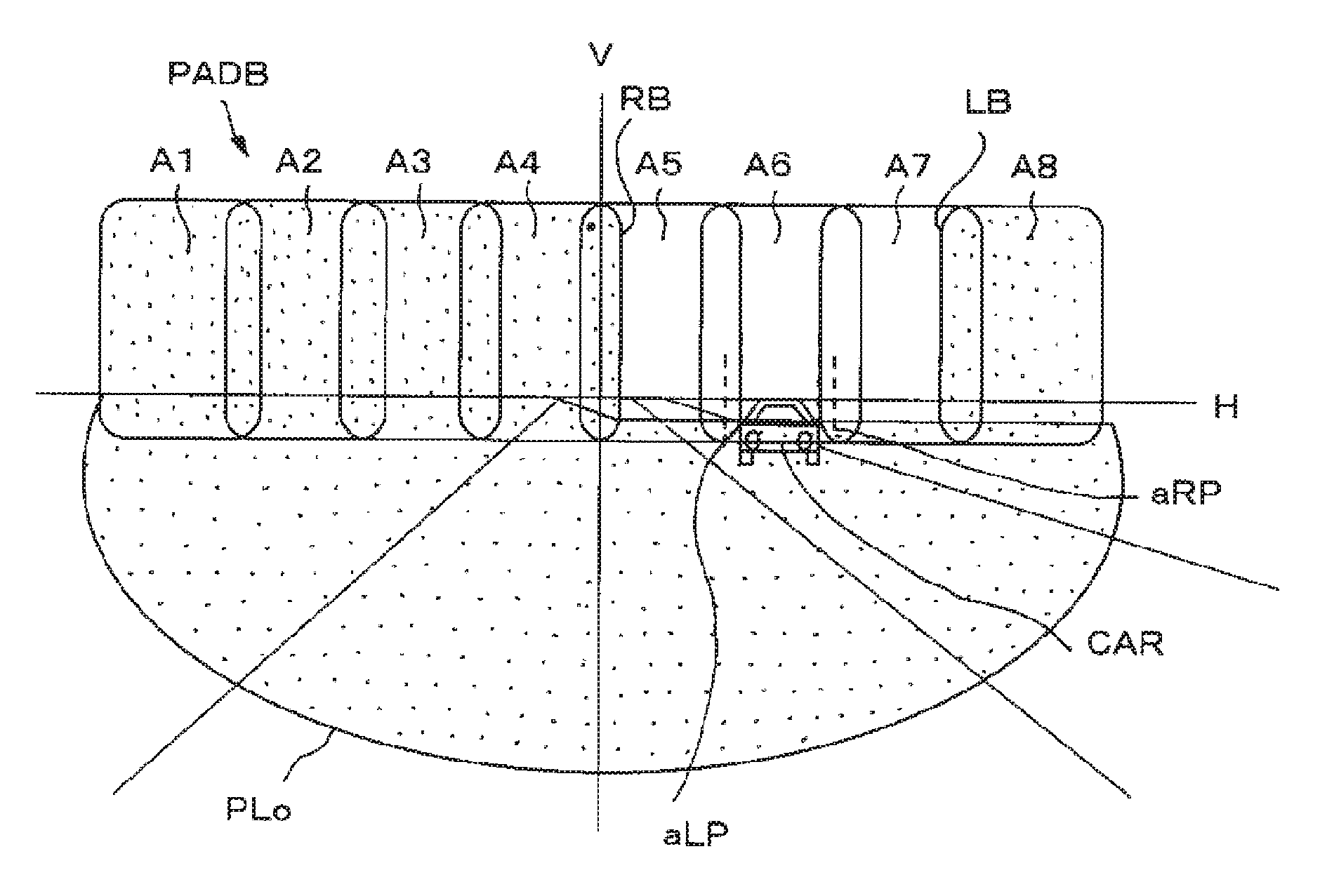
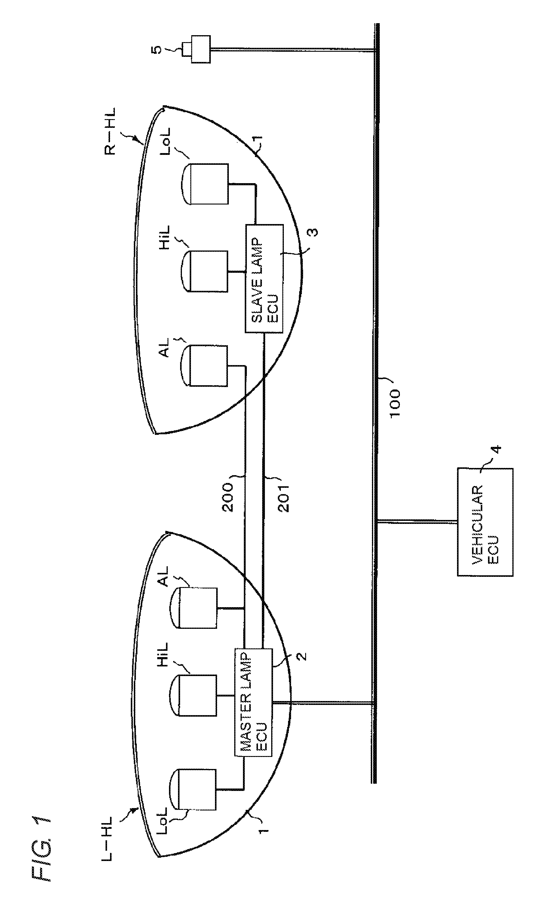
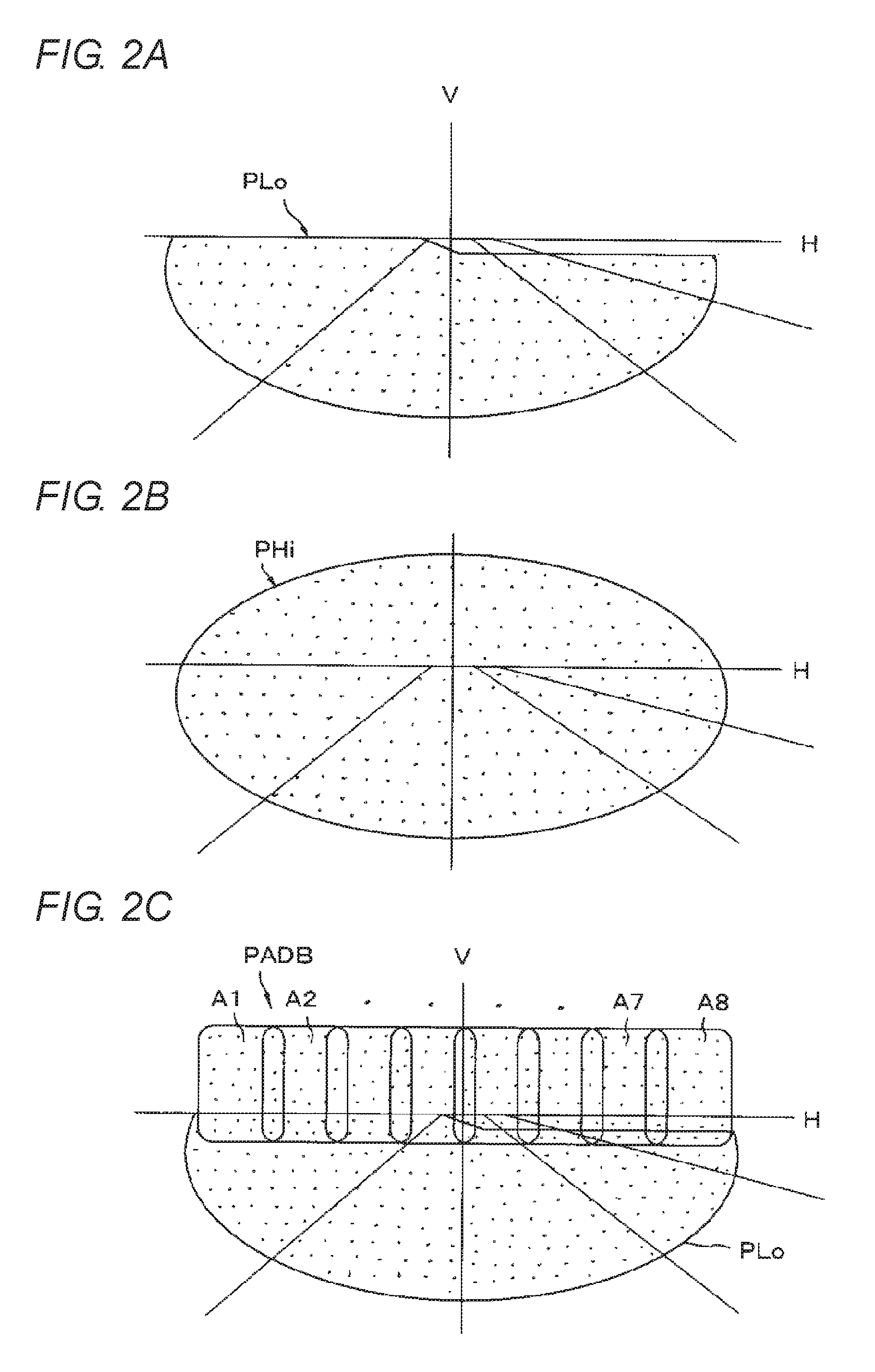
[0054]Next, an embodiment of the present invention will be described with reference to the drawings. FIG. 1 is a conceptual diagram showing the configuration of vehicular headlamps that employ an ADB light distribution control according to the invention. A left headlamp L-HL and a right headlamp R-HL which are disposed at front-left and front-right positions of a vehicle body of an automobile have approximately the same configurations. A low-beam lamp unit LoL, a high-beam lamp unit HiL, and an ADB lamp unit AL are disposed in each lamp housing 1. The low-beam lamp unit LoL and the high-beam lamp unit HiL will not be described in detail. Each lamp unit is a lamp unit in which LEDs (light-emitting diodes) are used as light sources, and emits light toward a region ahead of the self vehicle in a low-beam light distribution pattern PLo shown in FIG. 2(a) or a high-beam light distribution pattern PHi shown in FIG. 2(b) when lit.

[0055]FIG. 3 is a schematic front view of an LED array packa...

embodiment 2

[0079]Next, another embodiment of the invention will be described with reference to the drawings. FIG. 8 is a conceptual diagram showing the configuration of vehicular headlamps according to the embodiment. A left headlamp L-HL and a right headlamp R-HL which are disposed at front-left and front-right positions of a vehicle body of an automobile have approximately the same configurations. A low-beam lamp unit LoL, a high-beam lamp unit HiL, and an ADB lamp unit AL are disposed in each lamp housing 1001. The low-beam lamp unit LoL and the high-beam lamp unit HiL will not be described in detail. Each lamp unit is a lamp unit in which LEDs (light-emitting diodes) are used as light sources, and emits light toward a region ahead of the self vehicle in a low-beam light distribution pattern PLo shown in FIG. 9(a) or a high-beam light distribution pattern PHi shown in FIG. 9(b) when lit.

[0080]As shown in FIG. 10 which is a schematic plan view showing the configuration of each ADB lamp unit ...

embodiment 3

[0103]Next, a further embodiment of the invention will be described with reference to the drawings. FIG. 17 is a conceptual diagram showing the configuration of vehicular headlamps to which an ADB light distribution control according to the invention is applied. A left headlamp L-HL and a right headlamp R-HL which are disposed at front-left and front-right positions of a vehicle body of an automobile have approximately the same configurations. A low-beam lamp unit LoL, a high-beam lamp unit HiL, and an ADB lamp unit AL are disposed in each lamp housing 2001. The low-beam lamp unit LoL and the high-beam lamp unit HiL will not be described in detail. Each lamp unit is a lamp unit in which LEDs (light-emitting diodes) are used as light sources, and emits light toward a region ahead of the self vehicle in a low-beam light distribution pattern PLo shown in FIG. 18(a) or a high-beam light distribution pattern PHi shown in FIG. 18(b) when lit.

[0104]As shown in FIG. 19 which is a schematic ...


PUM


Abstract

The invention relates to a light distribution control method and a light distribution control device in which plural illumination regions are arranged in the left-right direction and illuminated by a headlamp in an ADB light distribution pattern, and vehicle positions of a vehicle ahead are detected and selected ones of the plural illumination regions are reduced in light quantity according to the detected vehicle positions. In this method and device, corrected vehicle positions are set that are obtained by adding margins to the detected vehicle positions in the left and right directions, respectively, and compared with the plural illumination regions. Illumination regions where the vehicle ahead exists are reduced in light quantity.

Description

TECHNICAL FIELD[0001]The present invention relates to a technique for controlling the light distribution of a vehicular headlamp, and more particularly, to a light distribution control method and a light distribution control device for a vehicular headlamp that can be subjected to ADB (adaptive driving beam) light distribution control.BACKGROUND ART[0002]ADB light distribution control has been proposed as one technique for producing a light distribution for preventing dazzling of the driver etc. of a vehicle(s) (hereinafter referred to “vehicle(s) ahead”) located in a region ahead of the self vehicle, such as a forward vehicle running in the same direction or an oncoming vehicle, while enhancing the effect of illumination of the region ahead of the self vehicle. In the ADB light distribution control, a vehicle ahead is detected by a vehicle position detecting device and a control is performed to reduce (to zero if necessary) the light quantity in a region where the detected vehicle ...

Claims


Application Information

Patent Timeline
Patent Type & Authority Patents(United States)
IPC IPC(8): B60Q1/02B60Q1/14F21S8/10B60Q1/38
CPCB60Q1/1423B60Q1/143F21S48/1154F21S48/1258F21S48/1747B60Q1/38B60Q2300/054B60Q2300/056B60Q2300/332B60Q2300/336B60Q2300/41B60Q2300/42B60Q2300/45F21Y2103/10F21S41/143F21S41/255F21S41/663F21W2102/155F21S41/151F21W2102/165B60Q1/381F21W2102/00
Inventor TANAKA, HIDETADAMASUDA, TAKESHIKOMATSU, MOTOHIROMURAMATSU, TAKAO
Owner KOITO MFG CO LTD
Learn More