Nesting container assembly

a container and assembly technology, applied in the field of nesting container assembly, can solve the problems of inefficiency and problems in the current use, containers or boxes are oftentimes extremely heavy, bulky and difficult to transport, containers or boxes are generally of a non-uniform shape and size, etc., and achieve the effect of maximizing the usable space of a pall

Active Publication Date: 2017-01-24
SUMMERS MATTHEW A
View PDF41 Cites 27 Cited by
  • Summary
  • Abstract
  • Description
  • Claims
  • Application Information

AI Technical Summary

Benefits of technology

[0008]The present invention is generally directed to a container that may engage, abut, interlock, or otherwise connect or nest with other like adjacent, adjoining or bordering containers positioned and stacked above, below, beside and end-to-end to one another. The containers of certain embodiments of the present invention are dimensioned in order to maximize the usable space of a pallet, including, but not limited to a 463-L Pallet, HCU-6 / E Pallet, or other pallets, when used in concert with other like containers. To secure the containers on a pallet or otherwise in a connected, adjoining relation to one another, the user may push or position the containers into adjacent like containers, either front-to-back, side-to-side, or on top of one another. The nesting and cooperative configuration of the containers are also structured to restrict or prevent lateral and horizontal slipping or movement between the containers, for example, during transport.
[0011]Yet another interlocking, mating or engaging portion of at least one embodiment may include a handle engaging portion that is structured and configured to receive and at last partially engage or retain a handle from an adjacent or adjoining container. The handle engage portion may thus slidingly receive the handle from an adjacent or adjoining container therein and thereby restrict movement between the containers in at least one direction.
[0013]Additional features may include single or double walled reinforced construction providing superior strength and integrity to the container. For example, in at least one embodiment, the container may include an upper lip or edge upon which the lid rests or engages. The upper lip or edge may be constructed with a reinforced double walled configuration providing added strength and integrity and allowing the container to withstand heavy stacked loads. The lip may be supported, for example, vertically, by at least one wall, whether single or double walled. The at least one wall may include a corrugated, honeycomb or other like configuration having a plurality of alternating recesses and protrusions that provide additional strength and integrity to the container, as a whole.

Problems solved by technology

A number of inefficiencies and problems exist in the currently used manner of transporting traditional containers to and from the pallets, and loading, stacking or unloading materials or items on or from the pallets for shipment.
The containers or boxes are oftentimes extremely heavy, bulky and difficult to transport, especially over unfinished surfaces (such as gravel, sand, grass, etc.) commonly present in the military environments.
Moreover, the containers or boxes, which are generally of a non-uniform shape and size, are then loaded onto the pallet—a time-consuming and extremely labor intensive task.
Once loaded, the non-uniform shape and size of the containers or boxes create an excessive amount of wasted space between the items or containers.
Finally, a packed pallet can oftentimes be unsteady and can collapse before, during or after shipment creating a dangerous situation and environment for crew and passengers of the vessel, ship or other vehicle used to transport the pallet.

Method used


Image

  • Nesting container assembly
  • Nesting container assembly
  • Nesting container assembly

Examples


Embodiment Construction

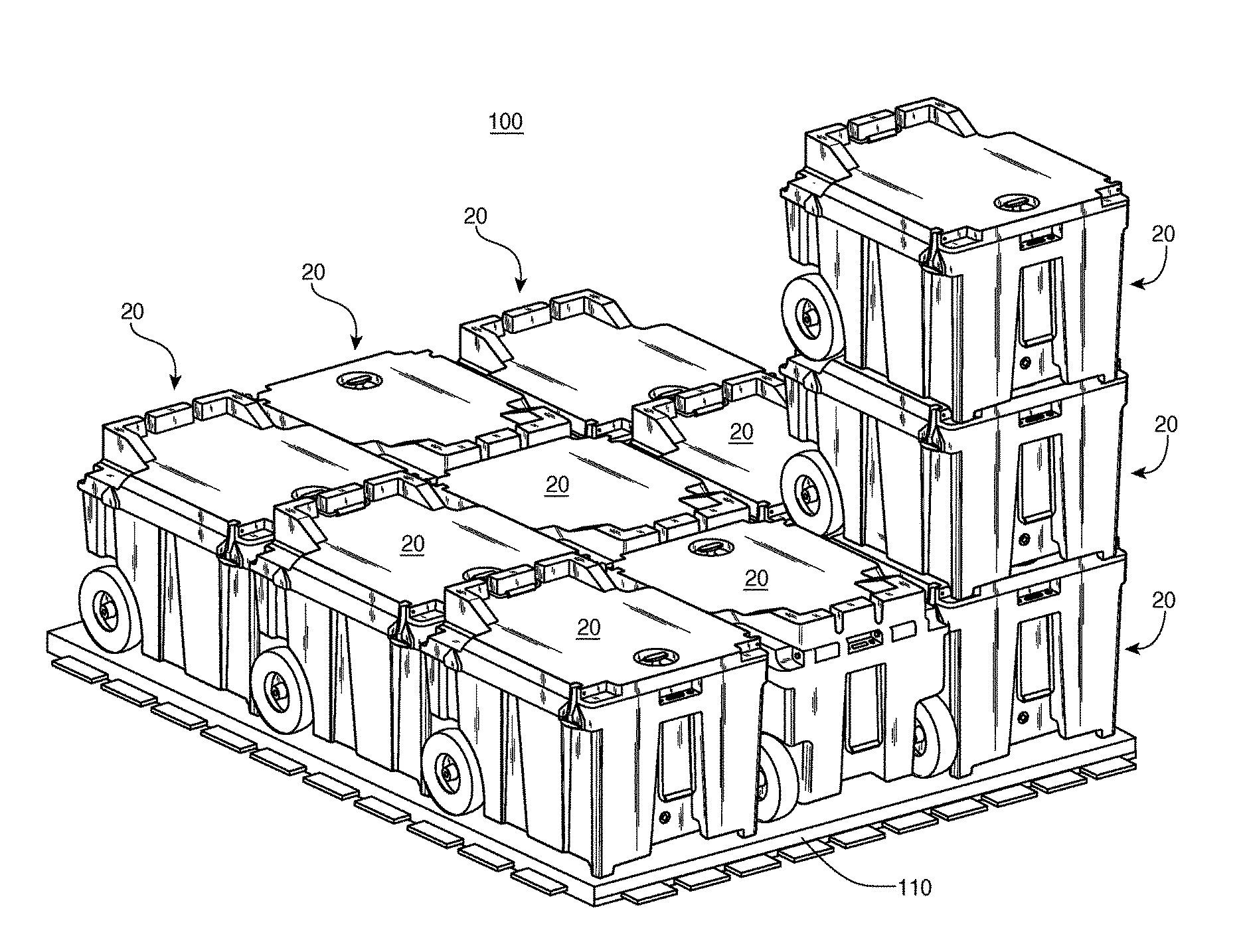
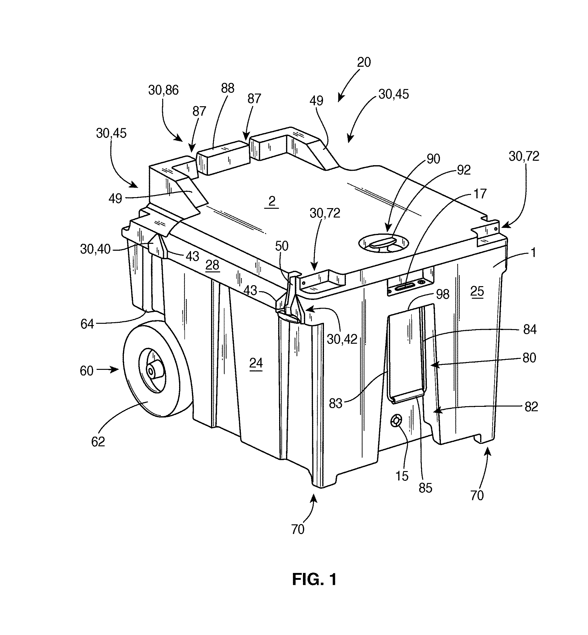
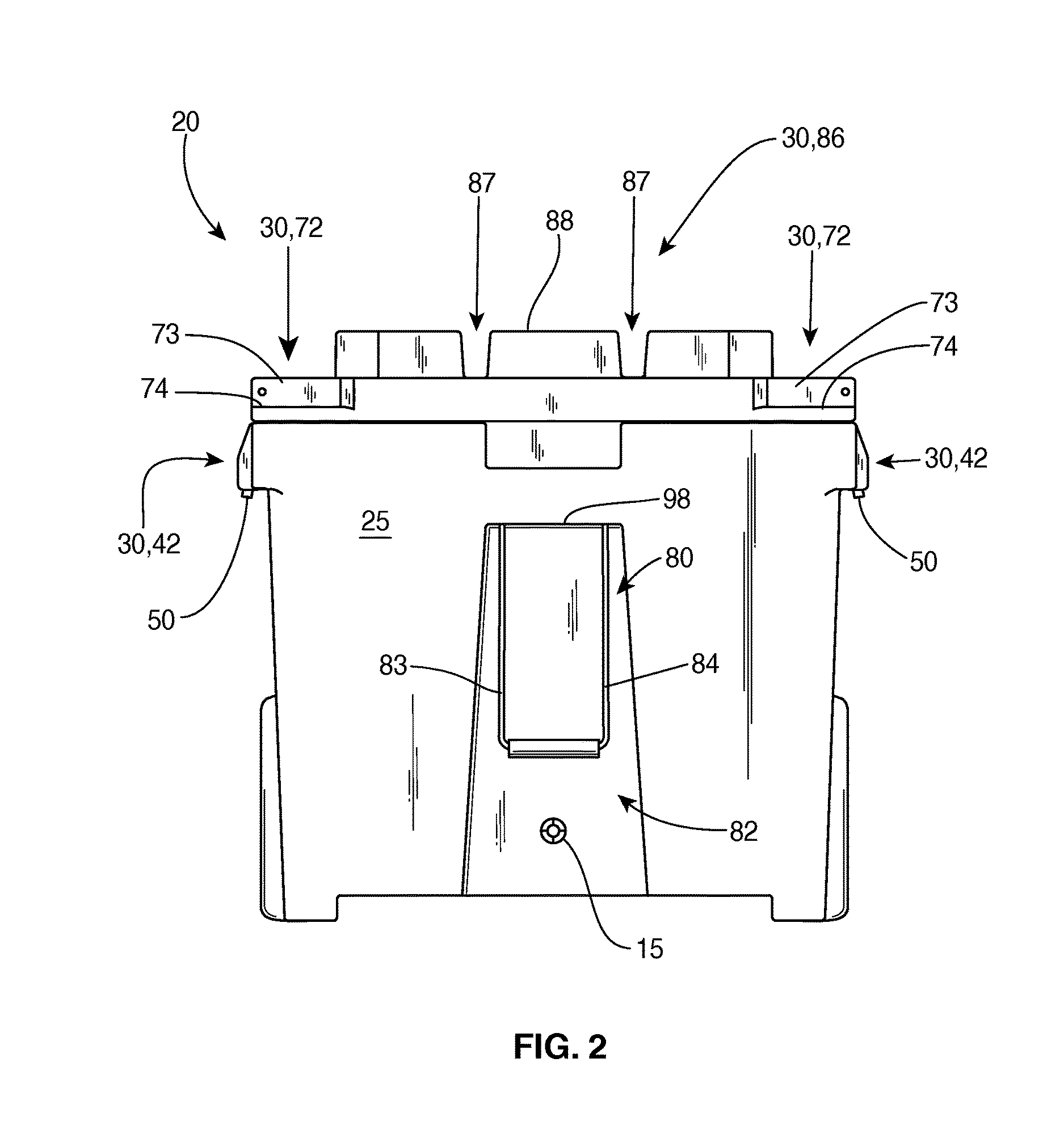
[0035]As shown in the accompanying drawings, and with particular reference to FIGS. 1 and 15, for example, the present invention is directed to a container 20 and container system or assembly 100 for facilitating the transportation or shipment of goods, materials, equipment, and other items. As described herein, certain embodiments of the container(s) 20 may, but need not be used in connection with standard pallet sizes, including, but not limited to a 463-L Pallet, HCU-6 / E Pallet, etc. For example, in at least one embodiment, the dimensions of the container 20 may be formed or constructed so that when it is interlocked with, connected to or placed side-by-side, end-to-end, and / or stacked with additional adjacent or adjoining containers 20 of a similar construction and configuration in order to form a container system or assembly 100, the container system or assembly 100 of at least one embodiment will fit on the pallet 110, and in certain embodiments may use or occupy substantially...


PUM


Abstract

An interlocking or engaging container and container system are presented herein. In particular, the system includes a plurality of adjacently disposed (side-by-side, end-to-end and stacked) containers that are dimensioned to maximize the available space on a pallet, for example, a 463-L Pallet, HCU-6 / E Pallet or other pallet. The containers include enlarged wheels, one or more support feet, and a handle assembly. The containers are configured to include a plurality of interlocking or engaging portions such as one or more wheel assembly receiving portions, one or more foot receiving portions, outer extensions or engaging portions, and a handle engaging portion. The Interlocking or engaging portions are configured to matingly engage or abut corresponding portions of an adjacent container and at least partially restrict movement there between.

Description

CLAIM OF PRIORITY / CROSS REFERENCE TO RELATED APPLICATION[0001]The present application is based on and a claim to priority is made under 35 U.S.C. §119(e) to provisional patent application Ser. No. 62 / 043,588, having a filing date of Aug. 29, 2014, the contents of which are incorporated herein their entirety by reference.FIELD OF THE INVENTION[0002]The present invention is directed to an interlocking or other container with enlarged wheels which, in certain embodiments, is structured and sized to maximize available space in a pallet (e.g., 463-L Pallet, HCU-6 / E Pallet, or other pallets), while reducing the time and work necessary for a user to load and unload the container, transport the container, and stack or load and unload the pallet.BACKGROUND OF THE INVENTION[0003]The transportation of goods, equipment, or materials is often conducted or facilitated by stacking or otherwise placing the items on a pallet for loading and subsequent unloading to and from transportation vehicles, i...

Claims


Application Information

Patent Timeline
Patent Type & Authority Patents(United States)
IPC IPC(8): B65D21/02B65D25/24B65D43/02B62B1/00B65D25/28
CPCB65D21/0215B65D25/24B65D25/28B65D43/02B62B1/006B65D21/0202B65D21/0223B65D25/20B65D25/2841B65D55/10B62B5/067B62B3/003B62B3/16B62B2207/02B62B3/004B62B1/008B62B2204/00B62B2207/00B65D21/0204B65D43/16
Inventor SUMMERS, MATTHEW A.
Owner SUMMERS MATTHEW A
Why Eureka
Try Eureka