Header track with stud retention feature

a technology of retaining feature and stud, which is applied in the direction of walls, building components, structural elements, etc., can solve the problems that the metal stud wall framing assembly that provided set attachment points at 8 inch or 4 inch on center in hopes of providing attachment points for all studs has not been successful, and achieves the effect of extra labor or cos

Active Publication Date: 2017-01-24
CEMCO LLC
View PDF7 Cites 37 Cited by
  • Summary
  • Abstract
  • Description
  • Claims
  • Application Information

AI Technical Summary

Benefits of technology

[0010]Once the studs are nested into the header track, the pre-bent vertical legs with slits provide a series of tabs that allow numerous locations to lock or secure the vertical studs in place and prevent lateral side to side movement of the studs along the length of the stud wall / header track / footer track. The stud can be installed by inserting the stud at about 90 degrees from its normal position and then rotating the stud into place, thereby outwardly deflecting the tab or tabs aligned with the stud. The tabs adjacent the stud remain inwardly bent to secure the stud in place. To move the stud to a different location, the installer can rotate the stud a half turn which will free up the stud out of the restrictions of the tabs.
[0013]For these reason it would be of great value to create a manufactured framing system that provides, in some configurations, the required vertical deflection movement, allows the studs to be placed anywhere within the wall, connects the stud to the track to prevent side to side or lateral movement along the wall length, is made from a solid track in at least an upper portion of the side flange that did not allow smoke, sound or light to travel through the wall, and does not require the extra labor or the cost for additional framing screws or crimping devises at each side of the stud at both top and bottom.

Problems solved by technology

In the past, metal stud wall framing assemblies that provided set attachment points at 8 inch or 4 inch on center in hopes to provide attachment points for all studs have not been successful because studs, although they cannot exceed the maximum allowable spacing of 16 inch or 24 inch, many times will be less than the maximum spacing in order to work around MEP's.

Method used


Image

  • Header track with stud retention feature
  • Header track with stud retention feature
  • Header track with stud retention feature

Examples


Embodiment Construction

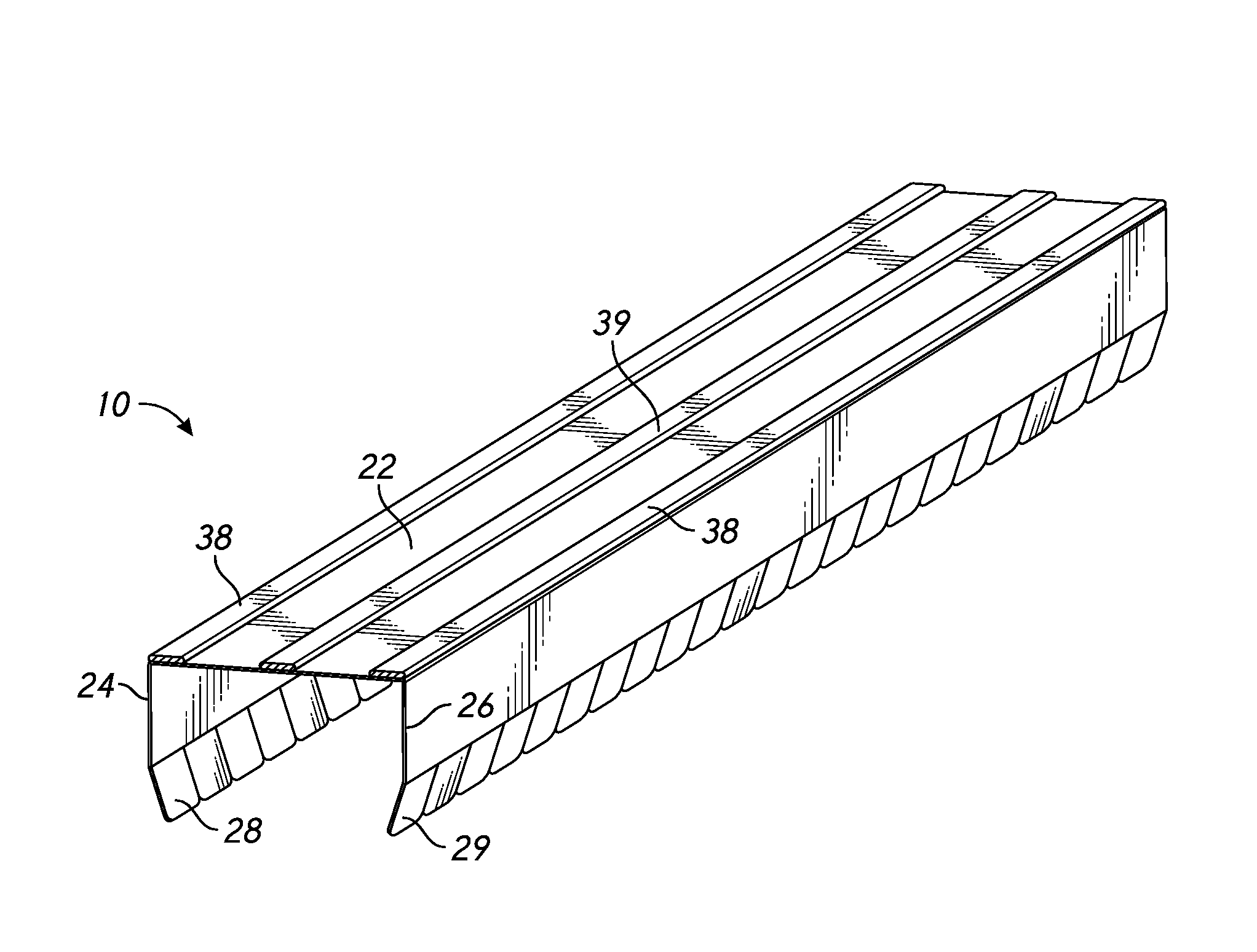
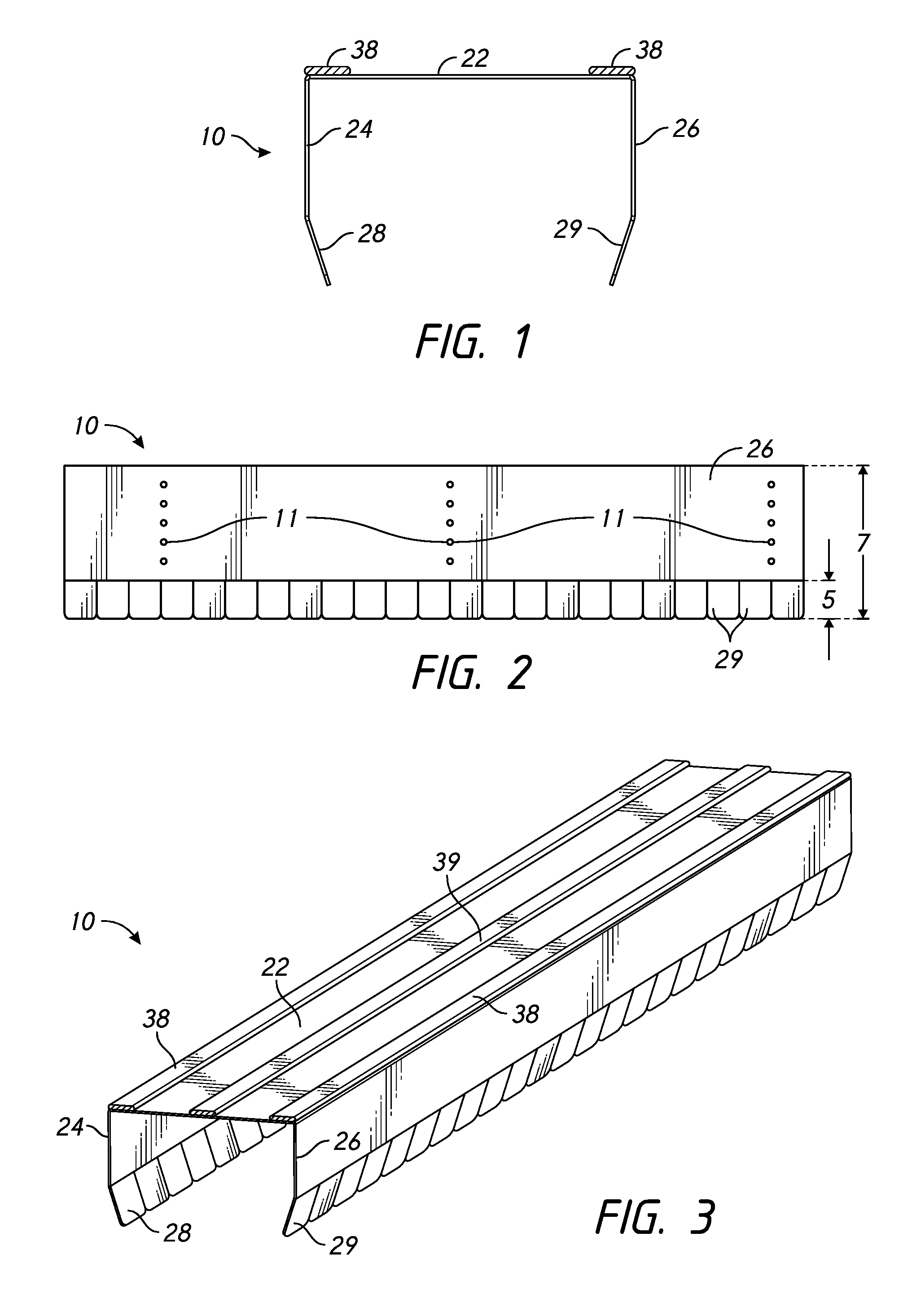
[0039]Several preferred embodiments provide a way to secure metal studs to the header track or bottom track without using mechanical screw fasteners. The C- or U-shaped header or bottom track includes a plurality of slits in one or both flanges of the track that form a plurality of tabs in the flanges of the track adjacent the free edge of the flanges. The slits extend partially up the legs or flanges of the track so that the bulk of the track is a solid uninterrupted C- or U-shape profile. The track can, in some embodiments, have fire-retardant material such as intumescent strips added to the surface of the back web of the track to provide fire rated wall assemblies according to UL-2079.

[0040]Referring to FIGS. 1-3, a first embodiment of a track 10 comprises a web 22 and two side flanges 24, 26. A lower end of each of the side flanges 24, 26 comprises a plurality of tabs 28, 29 that may be folded or bent inward towards the web 22 to secure a metal stud, as discussed in greater deta...


PUM

PropertyMeasurementUnit
widthaaaaaaaaaa
lengthaaaaaaaaaa
interior angleaaaaaaaaaa

Abstract

A track for a wall construction for use in building construction is disclosed. Embodiments can include a track having a plurality of bendable tabs that can be manipulated to grip or release wall studs to prevent lateral or side to side movement of the studs. Embodiments can include tracks which incorporate various geometries capable of receiving fire-retardant material, including but not limited to intumescent material.

Description

INCORPORATION BY REFERENCE TO ANY PRIORITY APPLICATIONS[0001]Any and all applications for which a foreign or domestic priority claim is identified in the Application Data Sheet as filed with the present application are hereby incorporated by reference herein.BACKGROUND OF THE INVENTION[0002]Field of the Invention[0003]The present invention generally relates to a metal stud and track framing system for use in building constructions, particularly for use in the interior and / or exterior wall of a building. In particular, the present invention relates to a fire-rated and non-fire rated track having a stud retention feature.[0004]Description of the Related Art[0005]A wall assembly commonly used in the construction industry includes a header track, bottom track, a plurality of wall studs and a plurality of wall board members, possibly among other components. A typical header track resembles a generally U-shaped (or some other similarly shaped) elongated channel capable of receiving or cov...

Claims


Application Information

Patent Timeline
Patent Type & Authority Patents(United States)
IPC IPC(8): E04B2/76E04B2/78E04B2/02E04C2/20E04B2/74
CPCE04C2/205E04B2/02E04B2/7457E04B2/767E04B2/789E04B2/7411E04B2002/0289E04C2003/0473E04B1/2403E04B1/944E04B2/721E04B2001/2415E04B2001/2463
Inventor PILZ, DONALD A.
Owner CEMCO LLC
Why Eureka
Try Eureka